Electricity alternating current (AC) is an electrical current where the flow of electrons periodically reverses direction, creating a sinusoidal voltage waveform that crosses zero multiple times per second. Unlike direct current (DC), which pushes steadily in one direction, AC's constantly changing magnitude and direction introduce unique behaviors like reactance, skin effect, and zero-crossing arcs that fundamentally change how we design, measure, and protect circuits.
The Core Mechanics: RMS, Peak, and Frequency
When you measure AC voltage with a standard multimeter, you are not seeing the maximum voltage the wire is actually carrying. You are seeing the Root Mean Square (RMS) value. RMS is a mathematical method of expressing an AC voltage in terms of the equivalent DC voltage that would produce the same heating effect (power dissipation) in a resistive load.
For a pure sine wave, the peak voltage is always the RMS voltage multiplied by the square root of 2 (approximately 1.414). Let's look at a standard North American residential outlet:
- Nominal RMS Voltage: 120V
- Peak Voltage: 120V × 1.414 = 169.7V
- Peak-to-Peak Voltage: 339.4V (from the positive peak to the negative peak)
- Frequency: 60 Hz (meaning it completes 60 full cycles per second, crossing zero 120 times per second)
Why does this matter on the bench? If you are selecting a capacitor to filter or couple a 120V AC line, a component rated for 150V DC will catastrophically fail because the AC line actually hits 169.7V at its peak. You must always size insulation and dielectric components for the peak voltage, not the RMS voltage. For deeper waveform mathematics, the All About Circuits AC Waveforms guide provides excellent baseline derivations.
What AC Changes in a Real Circuit
When you switch from DC to AC, resistance (R) is no longer the only force opposing current flow. AC introduces reactance (X), which is the opposition to current change caused by inductors and capacitors. Together, resistance and reactance form impedance (Z).
This changes three major things in a real installation:
- Phase Shift: In inductive loads (motors, transformers), the current waveform lags behind the voltage waveform. In capacitive loads, current leads voltage.
- Power Factor (PF): Because of phase shift, the simple DC power formula ($P = V imes I$) no longer yields real power in Watts. You must calculate Apparent Power (Volt-Amps, or VA) and multiply by the Power Factor. A 120V motor drawing 10A with a 0.8 PF consumes 960W of real power, but the wiring must be sized for 1200VA.
- Zero-Crossing Arcing: When a mechanical switch opens under a DC load, the arc sustains until the contacts are physically far enough apart. Under AC, the current naturally drops to zero 120 times a second (at 60Hz), which helps extinguish arcs, but the inductive kickback can cause severe voltage transients.
Where You Meet This in Practice
You interact with the quirks of electricity alternating current constantly in both DIY electronics and home wiring:
- Home Wiring (NM-B and THHN): The National Electrical Code (NEC) ampacity tables are based on RMS current heating. A 14 AWG copper wire is rated for 15A RMS, regardless of the 169.7V peak swinging through it.
- Dimmer Switches: Modern LED dimmers use TRIACs to "chop" the AC sine wave. By delaying the turn-on point after the zero-crossing, they reduce the RMS voltage reaching the bulb, dimming it without wasting power as heat like old rheostats did.
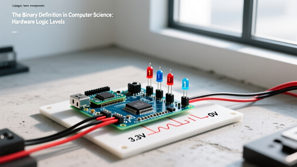
- Microcontroller Interfacing: When an ESP32 or Arduino needs to read mains voltage, you cannot feed AC into the ADC pin. You must use a step-down transformer or an isolated AC-to-DC module (like the HLK-PM01) to convert the AC to a safe 3.3V DC logic level, or use an optocoupler (like the H11AA1) to detect zero-crossings.
Scenario Walkthrough: Sizing a Solid-State Relay for an AC Motor
To understand how AC theory bites you in the real world, let's look at a common workbench failure involving an ESP32-WROOM-32, a solid-state relay (SSR), and an inductive load.
The Setup: A maker wants to automate a 120V, 1/2 HP basement sump pump using an ESP32. They wire the ESP32's GPIO pin to the input of a generic 25A Solid State Relay (Omron G3NA-225B), which switches the 120V AC hot line to the pump. The setup is housed in a 3D-printed enclosure.
The Numbers: A 1/2 HP motor at 120V draws approximately 9.8A of running current (RMS). The maker reasons that a 25A SSR provides a comfortable 2.5x safety margin over the 9.8A running load. The SSR costs about $12, while a 40A industrial SSR costs $28, so they go with the 25A model.
The Outcome: The system works perfectly for three weeks. Then, during a heavy rainstorm, the ESP32 triggers the SSR to turn on the pump. There is a loud pop from the enclosure, the SSR fails in a "closed" (shorted) state, and the pump runs continuously until the basement floods and the thermal overload on the pump motor eventually trips the breaker.
What Went Wrong: The maker sized the SSR for the RMS running current, ignoring two critical AC phenomena:
- Inductive Inrush (Locked Rotor Amps): AC induction motors draw massive current when starting. The LRA for this pump was roughly 6 times the running current: 9.8A × 6 = 58.8A. The 25A SSR's internal silicon die was instantly overwhelmed by the inrush surge.
- dv/dt Transients: When switching inductive loads, the phase shift between voltage and current means the TRIAC inside the SSR might be forced to turn off while voltage is still high across it. This rapid change in voltage ($dv/dt$) can falsely trigger the TRIAC back on, destroying the junction.
The Fix: To reliably switch this AC load, the maker needed to follow these steps:
- Upgrade to a 40A or 50A SSR specifically rated for inductive loads (e.g., Omron G3NA-250B) to handle the 58.8A LRA inrush.
- Install an RC snubber network (a 100-ohm resistor in series with a 0.1µF, 250V AC capacitor) across the SSR output terminals to suppress $dv/dt$ voltage spikes.
- Mount the SSR to a proper aluminum heatsink with thermal paste, as SSRs dissipate roughly 1.5W per amp of load current as heat.
Common Confusions: RMS vs. Peak and Power Math
The most frequent mistake hobbyists make with electricity alternating current is applying DC rules to AC components.
Confusion 1: "My 200V capacitor is fine for 120V AC."
False. 120V AC reaches 169.7V at the peak. A 200V capacitor is operating at 85% of its absolute maximum rating just on the baseline sine wave. Any minor grid surge or inductive kickback will push it past 200V, leading to dielectric breakdown and a short circuit. Always use capacitors rated for at least 250V AC (or 400V DC) on a 120V RMS line.
Confusion 2: "A 120V, 10A device uses 1200 Watts."
Only if the load is purely resistive (like a space heater or incandescent bulb). If the device is a PC power supply or an AC motor, it has a Power Factor of less than 1.0. A PC power supply drawing 10A at 120V with a 0.65 PF is only consuming 780W of real power, even though your wiring and breakers must handle the full 1200VA of apparent power.
Frequently Asked Questions
Q: Why do we use AC instead of DC for mains power distribution?
A: Historically and practically, AC allows the use of transformers to easily step voltage up for long-distance transmission (reducing $I^2R$ line losses) and step it back down for safe residential use. While modern High Voltage DC (HVDC) is used for specific long-haul grid ties today, AC remains the standard for local distribution due to the simplicity and low cost of AC transformers and switchgear.
Q: Does AC current actually flow "through" a capacitor?
A: Electrons do not physically cross the dielectric gap inside a capacitor. However, because the AC voltage is constantly reversing, the capacitor continuously charges and discharges. This creates a "displacement current" in the circuit that behaves exactly like current flowing through the component, governed by the capacitor's reactance ($X_c = 1 / (2 \pi f C)$).
Q: What is the "skin effect" in AC wiring?
A: At high frequencies, alternating current tends to travel only along the outer surface (skin) of a conductor, effectively reducing the wire's cross-sectional area and increasing its resistance. At standard 60Hz mains frequency, the skin effect is negligible for wires smaller than 1/0 AWG, but it becomes a major design factor in RF engineering and high-frequency switching power supplies.