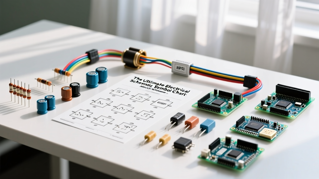

If you are reading a circuit diagram, the exact shape of a resistor or ground symbol depends entirely on which side of the ocean the engineer was sitting on. The two governing standards for any electrical schematic symbol chart are ANSI/IEEE 315 (dominant in North America) and IEC 60617 (dominant in Europe and most international markets). Knowing both is non-negotiable if you source designs globally, troubleshoot imported machinery, or contribute to open-source hardware projects.
This reference guide provides the direct translation between the two major standards, explains how to read qualifier modifiers, and outlines exactly what a schematic symbol will fail to tell you about a physical component.
How to Read This Electrical Schematic Symbol Chart
Before jumping to the table, you need to understand how to apply the columns to your specific installation and design environment. Unlike wire ampacity tables where you look up a temperature column, a symbol chart requires you to identify the regional and corporate standard governing your project.
- Which standard applies to you? If you are designing for a US-based defense contractor, UL certification, or legacy North American industrial panels, use the ANSI/IEEE 315 column. If you are designing for CE marking, exporting to the EU, or using modern open-source EDA tools like KiCad (which defaults to IEC), use the IEC 60617 column.
- How modifiers change the base symbol: Just as ampacity tables use derating factors to modify base current limits, schematic charts use qualifier modifiers to alter base component meanings. An arrow drawn diagonally through a base resistor symbol changes it from a fixed resistor to a variable resistor (potentiometer). A dashed line connecting two separate switch poles indicates they are mechanically ganged (moved by the same physical actuator). A circle enclosing a transistor indicates a discrete packaged part, while omitting the circle implies it is part of an integrated circuit.
The Complete Reference Table (ANSI vs. IEC)
The following table maps the most common discrete and electromechanical components. Both standards are maintained by authoritative bodies: ANSI/IEEE 315 is published by the Institute of Electrical and Electronics Engineers, while IEC 60617 is maintained by the International Electrotechnical Commission. For a deeper dive into historical symbol evolution, All About Circuits maintains an excellent open-source textbook chapter on the subject.
| Component | Ref Des | ANSI/IEEE 315 Shape | IEC 60617 Shape | Common Modifiers |
|---|---|---|---|---|
| Resistor (Fixed) | R | Zigzag line (typically 4-6 peaks) | Empty rectangle (oblong) | Arrow through = Variable/Pot; Arrow with right-angle bend = Trimmer |
| Capacitor (Non-Polarized) | C | Two parallel straight lines | Two parallel straight lines | One curved line (ANSI) or '+' sign (IEC) = Polarized/Electrolytic |
| Inductor / Coil | L | Series of scalloped humps (loops) | Series of half-circles or rectangle with internal loops | Parallel line through core = Iron core; Dashed line = Ferrite |
| Diode (Standard) | D | Triangle pointing to a vertical line | Triangle pointing to a vertical line (often inside a box) | Bent ends on line = Schottky; Zigzag line = Zener |
| NPN BJT Transistor | Q | Circle with vertical bar; arrow on Emitter points OUT | No circle; vertical bar; arrow on Emitter points OUT | Circle added in IEC = Discrete package; Multiple emitters = Multi-emitter BJT |
| PNP BJT Transistor | Q | Circle with vertical bar; arrow on Emitter points IN | No circle; vertical bar; arrow on Emitter points IN | Dashed circle = Matched pair; Diode across C-E = Integrated protection |
| N-Channel MOSFET | Q | 3-terminal or 4-terminal; solid line for enhancement, dashed for depletion | Similar, but bulk/body connection is explicitly drawn inside the channel box | Arrow on substrate pointing IN = N-Channel; Dashed channel line = Depletion mode |
| Relay Coil | K | Rectangle or circle with diagonal lines | Rectangle with a diagonal slash or internal coil symbol | Rectangle with 'U' shape = Latching relay; Diode parallel = Flyback protection |
| Switch (SPST) | S / SW | Gap in line with a hinged lever | Gap in line with a hinged lever (often drawn at an angle) | Dashed line to lever = Mechanical actuator; 'X' through gap = Normally Closed |
| Ground (Earth/Chassis) | GND | Three descending horizontal parallel lines | Single vertical line with three splayed diagonal lines (or empty downward triangle) | Horizontal lines with diagonal hatching below = Earth ground; Triangle = Signal ground |
| AC Voltage Source | V / AC | Circle with a sine wave inside | Circle with a sine wave inside (identical) | Arrows outside circle = 3-phase; Number of phases written next to symbol |
What This Chart Cannot Tell You (And Where to Look Next)
A schematic symbol is a logical abstraction, not a physical blueprint. Relying solely on an electrical schematic symbol chart will leave you blind to several critical physical realities when you move from EDA software to the soldering bench.
- Pinout Mapping: The symbol for an NPN transistor shows Collector, Base, and Emitter. It does not tell you that on a physical SOT-23 package, the Base is pin 1, the Emitter is pin 2, and the Collector is pin 3. You must consult the manufacturer's datasheet for the specific package variant.
- Physical Footprint and Clearances: A 10W power resistor and a 1/4W carbon film resistor share the exact same zigzag or rectangle schematic symbol. The chart cannot tell you that the 10W resistor requires a 15mm keep-out zone on your PCB to prevent scorching adjacent FR4 material and components.
- Internal IC Logic: Modern schematics frequently use large rectangular boxes with arbitrary pin numbers for microcontrollers (like an ESP32-WROOM-32) or motor drivers. The symbol hides the internal multiplexing, boot-strapping requirements, and pull-up configurations. Always cross-reference the functional block diagram in the silicon datasheet.
- Thermal and Power Derating: The symbol implies logical function, not thermal limits. A MOSFET symbol rated for 50A in the schematic might only safely handle 15A in your specific enclosure if the ambient temperature exceeds 40°C and you lack adequate copper pour for heatsinking.
Frequently Asked Questions
What is the difference between ANSI and IEC schematic symbols?
The primary difference is visual geometry, driven by historical drafting practices. ANSI/IEEE 315 (North America) tends to use pictorial representations—like the zigzag line for a resistor, which mimics the physical wire-wound construction of early resistors. IEC 60617 (International) favors abstract, modular geometric shapes—like a simple rectangle for a resistor. The IEC standard was designed to be easily drawn with basic drafting templates and to scale better in complex, dense logic diagrams.
How do you identify normally open (NO) and normally closed (NC) contacts?
In both ANSI and IEC standards, a switch or relay contact drawn with a gap and a lever resting away from the contact point is Normally Open (NO). If the lever is drawn resting on the contact point, or if there is a diagonal slash or 'X' crossing the gap, it is Normally Closed (NC). The "normal" state always refers to the unactuated, de-energized state of the physical component on the bench.
Which electrical schematic symbol chart standard does KiCad use by default?
KiCad's default symbol libraries are heavily biased toward IEC 60617 standards, reflecting its global, open-source developer base. For example, KiCad uses the IEC rectangle for resistors and the IEC splayed-line symbol for ground. However, because KiCad libraries are user-maintained, you will frequently find mixed standards in downloaded third-party libraries. It is best practice to run a symbol library audit and enforce a single standard across your custom project libraries before finalizing a PCB layout.
How are variable or adjustable components marked on a schematic?
Variable components are marked using a diagonal arrow crossing the base symbol. If the arrow is straight, it represents a user-adjustable component (like a front-panel potentiometer). If the arrow has a small right-angle bend or a flat bar at the end, it indicates a factory-set trimmer component (like a PCB-mounted trimpot used for calibration). This distinction is critical for mechanical design, as user-adjustable parts must be accessible via the enclosure, while trimmers are usually sealed inside.


