
When troubleshooting electromagnetic interference (EMI) or verifying safety clearances around high-voltage equipment, measuring standard potential difference (Volts) is not enough. You need to measure the electric field measurement units—specifically, the electric field strength expressed in Volts per meter (V/m). While a standard multimeter measures the voltage between two physical contact points, an E-field measurement quantifies the electrical pressure gradient radiating through free space. One V/m means that a charge placed in that field would experience a force equivalent to one Volt of potential difference across a one-meter distance.
In practical bench and jobsite work, V/m readings tell you if a power supply is poorly shielded, if a cable run is violating EMF exposure limits, or if a high-voltage busbar has sufficient clearance. Below is the exact methodology for capturing accurate V/m data using a digital multimeter (DMM) paired with a calibrated active probe.
Meter Setup & Probe Placement for V/m Testing
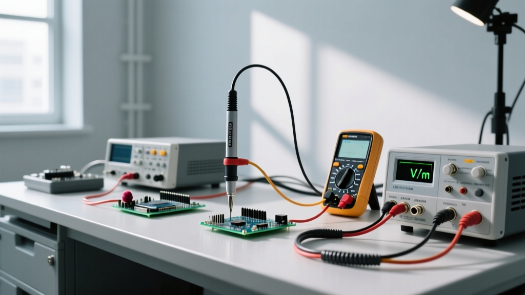
To measure V/m with a DMM, you cannot use standard test leads. You must use an active near-field E-field probe (such as a Langer EMV or Tektronix equivalent) that features a built-in preamplifier and a known effective antenna length. These probes are calibrated to output a scaled voltage—typically 1 mV on the DMM equals 1 V/m in the field.
Meter Setup Block
- Meter: True RMS DMM (e.g., Fluke 87V or Brymen BM257) with high input impedance (>10 MΩ).
- Dial Position: AC mV (for 50/60Hz mains E-fields) or DC mV (for static/DC fields).
- Lead Jacks: COM and VΩ. Use a BNC-to-banana plug adapter to connect the active probe’s output cable to the DMM.
- Range: Auto-range initially, then lock to the manual 200 mV range for maximum resolution (0.01 mV / 0.01 V/m) when measuring low-level ambient fields.
- Probe Power: Ensure the active probe’s internal 9V battery is fresh; a low battery causes the internal JFET buffer to compress, artificially capping high V/m readings.
Probe Placement Technique
Electric fields are vector quantities. The probe’s sensing element (usually a short dipole or monopole) must be aligned parallel to the expected field lines. For a standard wall cable, field lines radiate outward; hold the probe tip pointing directly at the cable. Maintain a strict, measured distance using a non-conductive (fiberglass or plastic) spacing jig. Even a 5 mm shift in distance at close range will drastically alter the reading due to the inverse-square drop-off of the field.
| Source / Equipment | Measurement Distance | Expected E-Field (V/m) | Field Drop-off Behavior |
|---|---|---|---|
| 120V NM-B Cable (Unshielded) | 10 cm (4 in) | 15 – 40 V/m | Drops to <5 V/m at 30 cm |
| 120V Metal-Clad (MC) Cable | 10 cm (4 in) | < 2 V/m | Near zero (shielded by armor) |
| Unshielded Benchtop SMPS (120W) | 5 cm (2 in) from case | 80 – 150 V/m | Highly localized, erratic |
| 480V 3-Phase Switchgear Busbar | 1 meter (3.2 ft) | 2,000 – 5,000 V/m | Follows 1/r gradient at distance |
| CRT Monitor / Older Flyback Transformer | 30 cm (12 in) from screen | 50 – 120 V/m | Directional, strongest at face |
Decoding the Numbers: Good vs. Bad E-Field Readings
Knowing the raw V/m number is only half the battle; you must know what constitutes an acceptable reading for your specific application. A "good" reading in a data center aisle might be considered a "bad" reading in a residential bedroom. The World Health Organization (WHO) and the ICNIRP provide general public exposure limits, but bench-level EMI troubleshooting requires much stricter internal thresholds to prevent signal integrity issues.
| Testing Scenario | Good Reading (Numerical) | Bad Reading (Numerical) | What a "Bad" Reading Indicates |
|---|---|---|---|
| Residential Bedroom (Sleeping Area) | < 10 V/m | > 50 V/m | Unshielded wiring behind the headboard or a nearby appliance with a failing EMI filter. |
| Benchtop SMPS (1 inch from enclosure) | < 50 V/m | > 200 V/m | Poor internal shielding, missing chassis ground bond, or a failing Y-capacitor in the input filter. |
| Data Center Hot Aisle (Near PDUs) | < 100 V/m | > 500 V/m | Improperly terminated high-voltage feeders or lack of metallic cable trays acting as a Faraday shield. |
| Audio Pre-Amp Chassis (Input Stage) | < 5 V/m | > 20 V/m | Ground loop, unshielded input traces, or missing conductive gasket on the enclosure lid. |
When evaluating these numbers, remember that electric fields are easily blocked by conductive materials. If you measure 150 V/m near a plastic enclosure, but the reading drops to 3 V/m when you place a grounded sheet of aluminum foil between the probe and the source, your issue is strictly electric field radiation, not magnetic field radiation (which would penetrate the foil).
Common Mistakes That Skew V/m Readings
Electric field measurements are notoriously fragile. The act of measuring the field often disturbs the field itself. Avoid these three critical errors that yield misleading data:
- The Ground Loop Antenna Effect: If your DMM is plugged into a grounded wall outlet via its charger, and the probe’s shield is tied to the DMM’s COM jack, the DMM’s power cord acts as a massive extension of your probe. You will measure the E-field of the room’s wiring, not the device under test. Fix: Run the DMM on battery power only, and use a double-shielded probe cable with the shield grounded only at the probe head.
- Ignoring the Inverse-Cube Law at Close Range: At distances greater than the physical size of the source, E-fields drop off at 1/r² or 1/r. But in the "near field" (typically within 3 to 5 cm of a PCB trace or small component), the field drops off at 1/r³. If you measure 100 V/m at 2 cm, moving the probe to 4 cm won't halve the reading to 50 V/m; it will slash it to roughly 12.5 V/m. Fix: Always document the exact probe-to-source distance in millimeters on your test sheet.
- Body Capacitance Loading: The human body is a conductive mass roughly equivalent to a 100 pF capacitor. If you hold the probe with your bare hand, your body absorbs and distorts the local field lines. Fix: Mount the probe on a fiberglass stand or hold it at the extreme end of a non-conductive PVC extension wand.
Safety Categories (CAT Ratings) for E-Field Work
Because E-field testing often requires you to bring measurement equipment dangerously close to energized conductors, your gear must be rated for the environment. According to Fluke safety guidelines and IEC 61010 standards, the CAT rating defines the meter's ability to withstand transient voltage spikes (let-through current) specific to the location.
- CAT II (Up to 1000V): Sufficient for measuring E-fields around standard plug-in appliances, benchtop power supplies, and single-phase receptacles.
- CAT III (Up to 600V/1000V): Required when measuring E-fields near fixed building wiring, distribution panels, subpanels, and heavy-duty motor feeds. The insulation and internal blast shields of a CAT III meter protect you if an arc flash occurs while you are positioning the probe.
- CAT IV (Up to 600V): Mandatory for E-field surveys at the service entrance, utility meter bases, and primary overcurrent protection devices.
By treating V/m as a precise, calculable metric rather than an abstract concept, you can diagnose shielding failures, verify safety clearances, and ensure your designs won't fail EMI compliance testing. Always pair your DMM with a calibrated active probe, control your spatial variables, and respect the CAT boundaries of your environment.