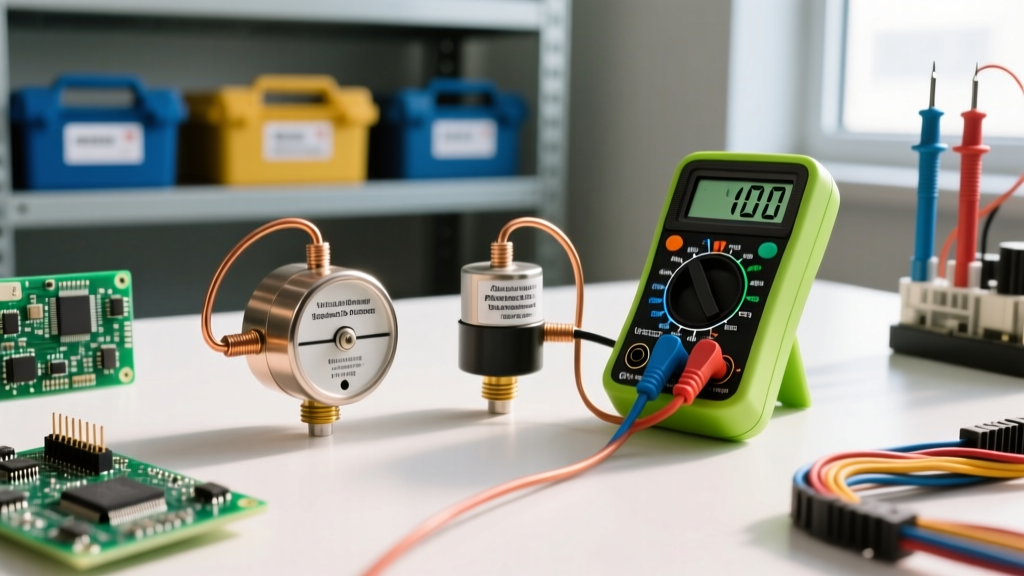
The electric field (E-field) in a capacitor is the electrostatic force per unit charge established between its conductive plates. Calculated as E = V/d (voltage divided by dielectric thickness), this field is the actual physical mechanism of energy storage. When you select a 100nF 50V multilayer ceramic capacitor (MLCC), you aren't just picking a capacitance value; you are selecting a specific dielectric thickness engineered to withstand a massive internal E-field without breaking down. Understanding how different materials manage this field is the difference between a circuit that runs for a decade and one that shorts out on the bench.
At the bench level, the E-field dictates everything from physical size to failure modes. A higher permittivity material allows for a thinner dielectric, shrinking the part but pushing the internal E-field closer to the material's breakdown threshold. Below is a data-dense breakdown of how common dielectric materials handle electrostatic stress.
Dielectric Breakdown and E-Field Limits
Dielectric strength measures the maximum E-field a material can withstand before it becomes conductive (breaks down). Relative permittivity (dielectric constant) determines how much energy it can store for a given thickness. Data sourced from standard materials physics references like Georgia State University HyperPhysics.
| Dielectric Material | Dielectric Strength (kV/mm) | Relative Permittivity (εr) | Resulting Capacitor Type |
|---|---|---|---|
| Barium Titanate (X7R Ceramic) | 10 - 20 | 1,000 - 4,000 | MLCC (Multilayer Ceramic) |
| Polypropylene (Film) | 600 - 700 | 2.2 | Power Film / Snubber |
| Aluminum Oxide (Electrolytic) | 700 - 1,000 | 9 - 10 | Aluminum Electrolytic |
| Tantalum Pentoxide | 500 - 600 | 27 | Solid Tantalum |
Notice the trade-off: Barium titanate has a massive permittivity, allowing MLCCs to be incredibly small, but its dielectric strength is relatively low. To compensate, manufacturers stack hundreds of microscopic ceramic layers in series and parallel. Film capacitors use polypropylene, which has a tiny permittivity but massive dielectric strength, making them physically large but ideal for high-voltage AC and snubber circuits where E-field spikes are severe.
Capacitor Type Comparison: Managing the Internal E-Field
Choosing the right capacitor is fundamentally about matching the component's E-field tolerance to your circuit's voltage profile. Here is how the major types compare when subjected to real-world electrical stress.
| Type | Construction | Tolerance | Tempco (Temp Stability) | Typical Use (E-Field Context) |
|---|---|---|---|---|
| MLCC (X7R/X5R) | Stacked ceramic layers | ±15% | ±15% over temp range | Decoupling, bypass. Good for steady DC, but capacitance drops under high DC bias E-field. |
| Film (Polypropylene) | Metallized film roll | ±5% | Very stable (±2%) | High-voltage AC, snubbers, audio. Immune to DC bias E-field capacitance loss. |
| Aluminum Electrolytic | Etched foil + liquid electrolyte | -20% / +80% | Poor (high drift) | Bulk filtering. The liquid electrolyte heals minor E-field dielectric breakdowns automatically. |
| Solid Tantalum | Sintered powder + MnO2/Polymer | ±10% | Stable | Space-constrained low-ESR filtering. Highly vulnerable to E-field transients and reverse voltage. |
Which type for which job? If you are designing a 400V DC bus snubber, the E-field will destroy an MLCC; you must use a polypropylene film capacitor. If you need 100µF of decoupling on a 3.3V FPGA rail where board space is tight, a solid tantalum or low-profile MLCC is required, as an electrolytic's ESL (Equivalent Series Inductance) will render it useless at high frequencies.
Decoding Markings and E-Field Derating Rules
Capacitor markings tell you the physical limits of the internal E-field. Misreading them is a primary cause of bench failures.
Reading the Codes
- Ceramic 3-Digit Code: A marking of
104means 10 followed by 4 zeros in picofarads (100,000 pF = 100nF). A105is 1µF. - Dielectric Letter Codes: Often stamped alongside the value.
X7Rmeans it operates from -55°C to +125°C with a ±15% capacitance change.Y5Vis a trap for beginners: it can lose up to 80% of its capacitance under a moderate DC bias E-field. Never use Y5V for timing or filtering. - Voltage Ratings: Usually printed directly on film and electrolytic caps (e.g.,
63V). On small SMD MLCCs, voltage is rarely printed; you must rely on your BOM or reel packaging.
The Derating Imperative
A 50V rating does not mean you should run the part at 50V. The E-field stress accelerates aging and increases the risk of catastrophic breakdown. Standard industry derating rules dictate:
- MLCC (X7R): Derate by 50%. Use a 50V part for a 24V rail. This accounts for DC bias capacitance loss and piezoelectric micro-cracking.
- Film: Derate by 20-30%. They handle E-field spikes well, but continuous overvoltage degrades the metallization.
- Tantalum: Derate by 50% minimum. Tantalum pentoxide is notoriously unforgiving of E-field transients.
When a solid tantalum capacitor experiences an E-field spike exceeding its derated limit, the dielectric breaks down, creating a short circuit. The resulting high current ignites the manganese dioxide cathode, which acts as an oxidizer. This causes a violent, self-sustaining fire. Always use a series resistor or substitute with polymer tantalum/ceramic in high-surge rails. For deeper safety guidelines, refer to All About Circuits capacitor safety protocols.
E-Field Failures: Visual Symptoms and Safe Substitution
When the internal E-field exceeds the dielectric's physical limits, the component fails. Recognizing the visual symptoms helps you diagnose root causes on the bench.
Common Failure Modes and Visual Symptoms
- Dielectric Breakdown (Short): The E-field tears electrons from the dielectric atoms, creating a conductive carbon track. Visual: Electrolytics will bulge at the vent or leak brown electrolyte. MLCCs may show a burnt, blackened crater or crack near the termination. Tantalums will appear scorched or completely exploded.
- Piezoelectric Flex Cracking (MLCC): Barium titanate is piezoelectric; the E-field causes it to physically expand and contract. Combined with PCB bending, this causes mechanical fractures. Visual: A hairline crack running diagonally from the solder pad edge into the ceramic body. Often invisible without a microscope or cross-section, but causes intermittent dead shorts.
- Dielectric Absorption (Memory Effect): The E-field aligns dipoles in the dielectric that fail to fully relax when discharged. Visual: None. The part looks perfect, but it will inject ghost voltages into sample-and-hold or precision integrator circuits.
How to Substitute Safely
When the exact BOM part is out of stock, follow these substitution rules to maintain E-field integrity:
- Never substitute a lower voltage rating. A 25V part on a 24V rail will experience an E-field near its breakdown threshold, leading to rapid DC bias capacitance loss and eventual shorting.
- Higher voltage is generally safe, but watch the physics. Substituting a 100V MLCC for a 50V MLCC means the manufacturer used thicker dielectric layers or fewer layers. The part will be physically larger (check pad clearance) and may have higher ESL.
- Never downgrade the dielectric class. Do not substitute an X7R with a Y5V or Z5U. The E-field will collapse the Y5V's capacitance by up to 80% under DC bias.
- Use 'Soft Termination' for high-stress areas. If substituting an MLCC near a board edge, mounting hole, or heavy connector, use a FlexiCap or Soft-Termination variant. These incorporate a conductive epoxy layer that absorbs mechanical stress before it can crack the ceramic dielectric.
- Electrolytic ESR matching. When substituting bulk filter capacitors, matching the capacitance and voltage isn't enough. You must match or beat the ESR (Equivalent Series Resistance). A higher ESR part will overheat and dry out under high ripple current, effectively increasing the internal E-field stress on the remaining oxide layer.
Mastering the E-field in capacitor selection moves you from blindly copying schematics to engineering robust power delivery networks. Always respect the dielectric's physical limits, derate aggressively for transients, and verify your substitutions against both electrical and mechanical stress profiles.