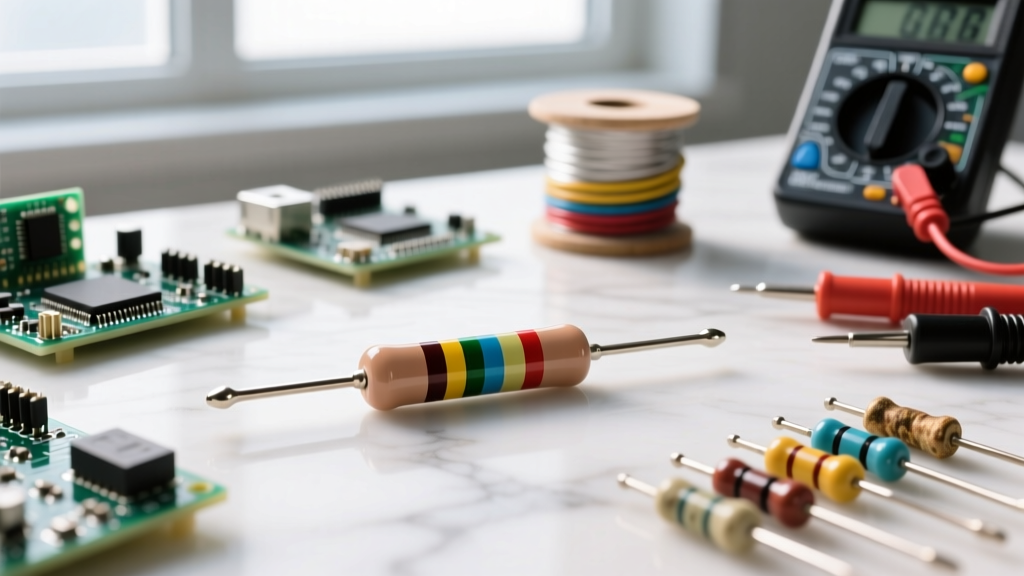
The positive side of a diode is the anode, and the negative side is the cathode. For a standard diode to conduct current (a state known as forward bias), the voltage at the anode must be higher than the voltage at the cathode by at least the component's forward voltage drop ($V_f$). If you connect it backward, it blocks current flow. Getting this orientation right is the single most common hurdle for beginners building power supplies, flyback circuits, or signal routers.
Decoding the Diode: Anode, Cathode, and the Symbol
Before you solder, you need to translate the schematic symbol to the physical component on your bench. The standard diode symbol consists of a triangle pointing toward a vertical line.
- The Triangle (Anode): The flat, rear side of the triangle represents the anode (positive side). The arrow points in the direction of conventional current flow (positive to negative).
- The Vertical Bar (Cathode): The line the arrow points to represents the cathode (negative side). Think of it as a physical wall blocking reverse current.
Translating this to physical through-hole components like the classic DO-41 package (e.g., 1N4007), the cathode is marked by a contrasting band or stripe printed on the body. For LEDs, which are also diodes, the cathode is indicated by the shorter leg, a flat edge on the plastic lens, and the larger internal anvil structure. In surface-mount devices (SMD) like the SOD-123 or SOT-23 packages, look for a printed line, a laser-etched bar, or a colored band on the plastic mold to identify the cathode.
Operation Regions and Biasing Data
Selecting and biasing a diode requires understanding which operational region your circuit demands. You do not just 'drop a diode in'; you engineer the anode-to-cathode voltage ($V_{AK}$) to force the component into a specific state. Below is the definitive reference for diode operation regions.
| Operation Region | Bias Condition | Anode-Cathode Voltage ($V_{AK}$) | Current Flow | Typical Application |
|---|---|---|---|---|
| Forward Bias | $V_A > V_K$ | $> V_f$ (e.g., >0.7V for Silicon) | High (mA to tens of Amps) | Rectification, signal routing, power OR-ing |
| Reverse Bias | $V_A < V_K$ | $< 0V$ (down to $-V_R$ rating) | Leakage ($\mu A$ to nA) | Blocking, isolation, reverse polarity protection |
| Breakdown | $V_A \ll V_K$ | $< -V_{BR}$ (Breakdown Voltage) | High (Avalanche/Zener effect) | Voltage regulation, transient clamping |
| Zero Bias | $V_A = V_K$ | $0V$ | $0A$ | Equilibrium (unused/floating state) |
How to bias for the job: If you are building an AC-to-DC rectifier, you want the diode in Forward Bias during the positive half-cycle and Reverse Bias during the negative half-cycle. You must ensure the peak inverse voltage (PIV) of your AC source never exceeds the diode's Reverse Bias maximum rating ($V_R$), or you will accidentally push it into the Breakdown region, destroying a standard rectifier. If you want breakdown behavior for voltage regulation, you specifically select a Zener diode and bias it in reverse.
Safe Default Part Numbers and Ratings
When prototyping or repairing boards, keep these five default diodes in your bench kit. They cover 95% of general-purpose hobbyist and industrial control applications. Pricing reflects typical 2026 distributor rates for small quantities.
| Part Number | Type | Max Reverse Voltage ($V_R$) | Forward Current ($I_F$) | $V_f$ (Typical) | Approx. Cost |
|---|---|---|---|---|---|
| 1N4148 | Small Signal (DO-35) | 100V | 300mA | 1.0V @ 10mA | $0.02 |
| 1N4007 | Standard Rectifier (DO-41) | 1000V | 1.0A | 1.1V @ 1A | $0.03 |
| 1N5819 | Schottky (DO-41) | 40V | 1.0A | 0.6V @ 1A | $0.05 |
| 1N5349B | Zener 12V (DO-201) | 12V ($V_Z$) | 5.0W (approx 400mA) | 12.0V @ 100mA | $0.15 |
| BAT54C | Dual Schottky SMD (SOT-23) | 30V | 200mA (per diode) | 0.4V @ 100mA | $0.04 |
Bench Tip: Never use a 1N4148 for power rectification. Its 300mA limit and high forward voltage at 1A will cause immediate thermal failure. Always default to the 1N400x series for mains or high-current DC, and use Schottkys (1N5819) when you need to minimize voltage drop in low-voltage (e.g., 5V or 12V) solar or battery circuits.
Application Circuit: 12V Relay Flyback Protection
One of the most critical applications of diode polarity is the flyback (or freewheeling) diode used across inductive loads like relay coils or solenoids. When you switch off an inductor, the collapsing magnetic field generates a massive reverse-polarity voltage spike that will instantly destroy your driving transistor.
Here is a complete, tested circuit for driving a 12V automotive-style relay using a 2N2222 NPN transistor, protected by a 1N4007 diode.
Component List
- Q1: 2N2222 NPN Bipolar Junction Transistor
- R1: 1kΩ, 1/4W base resistor
- K1: 12V DC Relay (coil resistance approx. 120Ω, drawing ~100mA)
- D1: 1N4007 Rectifier Diode (Flyback)
- Power: 12V DC Source
Wiring and Polarity Rules
- Connect the 12V source to one side of the relay coil (Pin 86 on standard automotive relays).
- Connect the other side of the relay coil (Pin 85) to the Collector of the 2N2222 transistor.
- Connect the Emitter of the 2N2222 to Ground (0V).
- Connect the 1kΩ resistor between your microcontroller GPIO (e.g., Arduino Pin 8) and the Base of the 2N2222.
- The Critical Diode Step: Place the 1N4007 in parallel with the relay coil. The Cathode (stripe) must connect to the +12V side of the coil. The Anode must connect to the Collector side of the coil.
Why this polarity? During normal operation, the cathode is at +12V and the anode is at ~0.2V (transistor saturation voltage). The diode is in Reverse Bias and does nothing. When the transistor turns off, the coil's inductive kick pulls the collector voltage negative (below ground). Suddenly, the anode is at a higher potential than the cathode relative to the spike. The diode snaps into Forward Bias, creating a short loop that safely dissipates the inductive energy as heat, clamping the voltage spike to roughly -0.7V and saving your transistor.
Failure Modes and Multimeter Testing
Diodes generally fail in two distinct ways. A short circuit occurs when excessive forward current causes thermal runaway, melting the silicon junction and fusing the anode to the cathode. An open circuit happens when a massive transient surge (like a lightning strike on a mains line) vaporizes the internal bond wire, acting like a blown fuse. According to Fluke's official testing guidelines, you should never use the standard 'continuity' beeper mode to test a diode, as the test voltage is often too low to forward-bias the junction.
Step-by-Step Multimeter Diode Test
Use a digital multimeter (DMM) set to the dedicated Diode Test mode (usually indicated by a diode symbol on the dial). This mode outputs enough voltage (typically 2V to 3V) to forward-bias the junction and displays the actual $V_f$ drop.
- De-energize the circuit: Never test a diode in a live circuit. Remove power and discharge any large capacitors. For the most accurate reading, desolder at least one leg of the diode to isolate it from parallel paths.
- Forward Bias Test: Touch the Red (positive) probe to the Anode and the Black (negative) probe to the Cathode. A healthy silicon diode will read between 0.500V and 0.800V. A Schottky will read 0.200V to 0.400V.
- Reverse Bias Test: Swap the probes. Red to Cathode, Black to Anode. A healthy diode will read 'OL' (Over Limit) or '1', indicating infinite resistance and successful blocking.
- Diagnose Failures:
- If both directions read 0.000V (or trigger the continuity beep), the diode is shorted. Throw it away.
- If both directions read 'OL', the internal bond wire has snapped and the diode is open. Throw it away.
- If the reverse bias test reads a low, fluctuating voltage instead of 'OL', the junction is leaking and the component is degraded.
Mastering diode polarity is not just about memorizing which side has the stripe; it is about visualizing the voltage differential across the junction in real-time. Whether you are routing signals with a 1N4148 or clamping inductive spikes with a 1N4007, always verify your anode and cathode orientations against the schematic before applying power. For deeper theoretical analysis of semiconductor junctions, refer to the comprehensive guides at Electronics Tutorials or the foundational texts on All About Circuits.