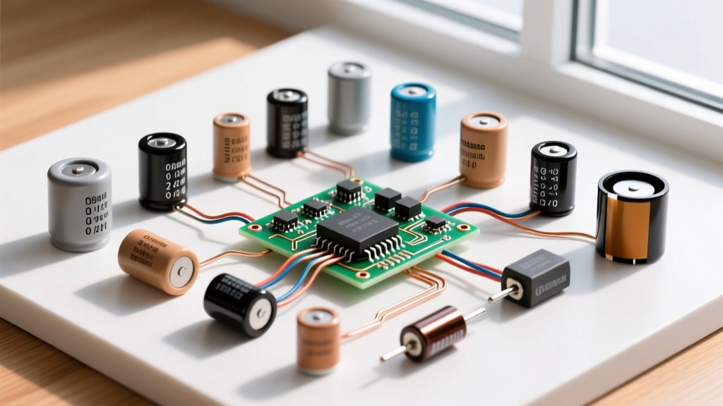

Capacitor problems rarely announce themselves with a bang unless it is a tantalum component catching fire. Most failures are silent: a gradual rise in Equivalent Series Resistance (ESR) that starves a microcontroller of transient current, or a microscopic flex-crack in a multilayer ceramic capacitor (MLCC) that shorts a 3.3V rail to ground. Diagnosing these issues requires moving beyond simple capacitance measurements to understand dielectric behavior, thermal limits, and physical stress. When a board comes across the bench dead, the capacitor is often the culprit. Here is how to identify the failure, read the physical markings, and select an exact, reliable replacement.
Decoding Capacitor Markings and Codes
Before you can substitute a part, you must know what you are looking at. Through-hole and surface-mount capacitors use different coding standards, and misreading a multiplier by one zero will shift your cutoff frequency by a decade.
The 3-Digit Ceramic Code
Most ceramic and film capacitors use a three-digit EIA code. The first two digits are the significant figures, and the third digit is the multiplier (number of zeros), expressed in picofarads (pF).
- Example: A capacitor marked
104means 10 × 10^4 pF = 100,000 pF = 100 nF = 0.1 µF. - Example: A capacitor marked
473means 47 × 10^3 pF = 47,000 pF = 47 nF.
Tolerance and EIAJ Voltage Codes
A trailing letter indicates tolerance (J = ±5%, K = ±10%, M = ±20%). Smaller SMD electrolytics and tantalums often use EIAJ alphanumeric voltage codes instead of printing the voltage directly.
| Code | Voltage Rating | Letter | Tolerance |
|---|---|---|---|
| 0J | 6.3V | J | ±5% |
| 1A | 10V | K | ±10% |
| 1C | 16V | M | ±20% |
| 1E | 25V | Z | +80% / -20% |
| 1V | 35V | ||
| 1H | 50V |
The Capacitor Type Comparison Matrix
Selecting the right dielectric is just as critical as selecting the right capacitance value. Swapping a ceramic for an electrolytic in a high-frequency switching regulator will result in immediate failure due to ESR limits.
| Dielectric Type | Construction | Typical Tolerance | Tempco / Stability | Best Application | Avoid Using For |
|---|---|---|---|---|---|
| MLCC (Class I - C0G/NP0) | Ceramic layers | ±1% to ±5% | Ultra-stable (0 ±30 ppm/°C) | RF filters, precision timing, PLL loops | High capacitance bulk storage |
| MLCC (Class II - X7R/X5R) | Ceramic layers | ±10% to ±20% | Moderate drop with DC bias & temp | Decoupling, bypass, general I/O filtering | Precision analog signal coupling |
| Aluminum Electrolytic | Etched foil + liquid electrolyte | -20% to +80% | Poor (dries out over time, high ESR) | Bulk energy storage, low-freq power filtering | High-frequency switching node decoupling |
| Polymer / Hybrid Aluminum | Foil + conductive polymer | ±20% | Excellent (ultra-low ESR, stable) | Switching regulator outputs, high ripple current | High voltage (>80V) applications |
| Solid Tantalum | Sintered pellet + MnO2/Polymer | ±10% to ±20% | Good, but prone to thermal runaway | Space-constrained bulk decoupling on low-V rails | High ripple current, un-clamped power inputs |
| Film (Polypropylene/PET) | Metallized wound film | ±1% to ±10% | Excellent, self-healing | AC line filtering, motor run, audio crossovers | Compact SMD high-density boards |
Visual and Electrical Failure Modes
Capacitors fail in distinct ways depending on their chemistry and the stress applied. Refer to the Cornell Dubilier Technical Guides for deep-dive physics on aluminum electrolytic degradation.
| Capacitor Type | Primary Failure Mode | Visual Symptoms | Electrical Symptoms (Meter/Scope) |
|---|---|---|---|
| Aluminum Electrolytic | Electrolyte boil-off / drying | Dome bulging, vented bottom, brown crust on leads | Capacitance drops 30%+, ESR spikes above 1Ω |
| MLCC (Ceramic) | Mechanical flex-cracking | Hairline crack near PCB edge, mounting hole, or V-score | Dead short (low ohms) or intermittent open circuit |
| Solid Tantalum | Thermal runaway / dielectric breakdown | Charred board, melted epoxy, sometimes literal flames | Dead short (often takes out the upstream fuse or LDO) |
| Film | Metallization vaporization (corona discharge) | Swollen casing, melted end seal, no external crust | Gradual capacitance loss, increased dissipation factor (DF) |
Safe Substitution Rules and DC Bias Derating
When the exact BOM part is out of stock or obsolete, you must substitute safely. Following these rules prevents latent field failures.
- Voltage Can Go UP, Never DOWN: Swapping a 16V cap for a 25V cap is safe. Swapping 25V for 16V is a fire hazard. However, larger voltage ratings often mean larger physical footprints, which may not fit the PCB pads.
- Respect DC Bias Derating (Class II Ceramics): This is where most hobbyists and junior engineers fail. An X7R or X5R MLCC loses capacitance as DC voltage is applied. A 10µF, 16V X7R capacitor might only provide 2µF of actual capacitance when biased at 12V DC. If substituting, either choose a higher voltage rating (e.g., 25V or 50V for a 12V rail) or parallel multiple smaller values to mitigate the bias drop.
- Temperature Rating Must Match or Exceed: Never replace a 105°C rated electrolytic with an 85°C part in a power supply. The 105°C part will last up to 4 times longer in the same thermal environment.
- ESR Matching in Switching Supplies: If the original part was a Low-ESR or Polymer capacitor, a standard general-purpose electrolytic will overheat and vent within weeks due to high RMS ripple current. Check the datasheet for ripple current ratings (measured in mA), not just ESR.
- Polarity in Signal Paths: Never substitute a polarized capacitor (electrolytic/tantalum) for a non-polarized one (ceramic/film) in AC coupling, audio signal paths, or integrator circuits where the voltage swings below ground.
Decision Tree: Picking the Right Replacement
Use this decision path to terminate your troubleshooting with a concrete, reliable part selection. This framework assumes you are repairing a modern DC-DC buck converter output filter that has suffered a failed capacitor.
| Diagnostic Question | If YES | If NO |
|---|---|---|
| Is the failed part on the output of a switching regulator (>100kHz)? | Proceed to next step. High ripple current is expected. | Standard bulk storage rules apply. Match capacitance and voltage. |
| Did the original standard electrolytic fail prematurely (bulging/vented)? | Ripple current exceeded the part's rating. You MUST upgrade to Low-ESR. | Failure was likely thermal or age-related. Match original specs. |
| Is the PCB space constrained (e.g., max height 5mm)? | Use Solid Polymer Tantalum or SMD MLCC arrays. | Proceed to final pick for maximum reliability. |
| Final Decision Node | Concrete Pick: Upgrade to a Hybrid Polymer Aluminum Electrolytic. | |
The Concrete Recommendation
If you are replacing a failed 100µF standard electrolytic on a 5V switching regulator output, do not just buy another generic 100µF 10V electrolytic. The high-frequency ripple will kill it again.
Default Pick: Panasonic EEH-ZA1V101 (100µF, 35V, Hybrid Polymer SMD).
Why this part? Panasonic's ZA series uses a hybrid construction (conductive polymer + liquid electrolyte). This gives you the ultra-low ESR of a polymer cap (typically 20mΩ) to handle massive ripple current without overheating, combined with the self-healing properties of the liquid electrolyte to survive voltage spikes. It operates up to 105°C and will outlast a standard liquid-only electrolytic by a factor of five in the exact same thermal environment. When in doubt on a switching node, hybrid polymer is the definitive upgrade path.


