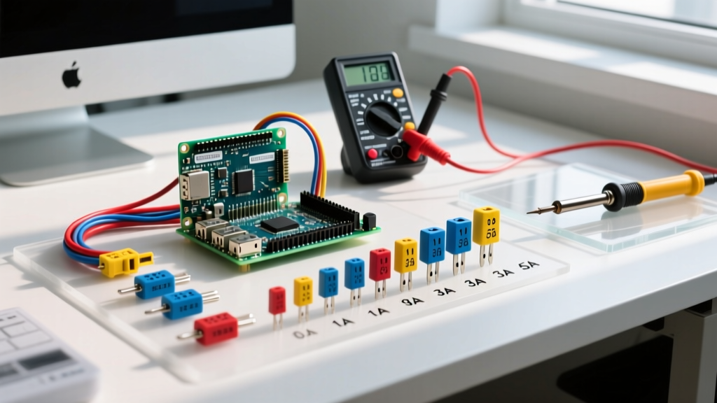

What is a Fuse? (Defining the Core Component)
To define a fuse in practical electrical terms: it is a sacrificial, single-use overcurrent protection device containing a calibrated metal element that melts (opens) when current exceeds its rating for a specific duration. Unlike electromechanical breakers that use bimetallic strips and solenoids to trip a mechanical latch, a fuse relies purely on the physics of thermal heating (the I²t melting integral). When the element melts, it creates an air gap, extinguishing the arc and permanently breaking the circuit to prevent wire insulation melt-down or electrical fires.
On the bench or in a panel, you will most commonly encounter cartridge fuses (like the Bussmann FRS-R-30 or Littelfuse FLNR series). While they look simple, treating them as just 'wire that melts' leads to catastrophic nuisance tripping or, worse, panel explosions during a dead short. To specify them correctly, we have to look at how they interact with the rest of the electromechanical control panel.
Rating Table: Fuses vs. Electromechanical Protectors
A common mistake is looking only at the ampere rating. While a fuse itself does not have a 'coil' (it is a passive thermal device), it is almost always wired upstream of electromechanical contactors or relays. Understanding the full rating table—including coil voltages for the downstream devices and the breaking capacity of the fuse—is critical for panel design.
| Parameter | Cartridge Fuse (e.g., Bussmann FRS-R-30) | Electromechanical Contactor (e.g., Schneider TeSys D) |
|---|---|---|
| Coil Voltage | N/A (Passive Device) | 24VDC, 120VAC, 240VAC (Control Circuit) |
| Contact / Terminal Rating | 30A Continuous at 600VAC | 32A (AC-3 Motor Load) / 50A (AC-1 Resistive) |
| Breaking Capacity (kAIC) | 200 kA @ 600VAC (Current Limiting) | Not rated to break faults (Relies on upstream fuse) |
Which rating column governs this load? For steady-state operation, the Contact/Ampere Rating governs. You size the fuse to protect the wire and the contactor's continuous thermal limit. However, during a catastrophic dead short (e.g., a tool dropped across busbars), the Breaking Capacity (kAIC) governs. If your panel has 40,000 amps of available fault current from the utility transformer, and you install a standard glass fuse with a 10kA breaking capacity, the fuse will violently explode before it can clear the fault. Always match or exceed the available fault current.
Coil vs. Contact Side Wiring and Protection
When integrating fuses into a motor control center or automation panel, you must separate the contact side (the high-power load circuit) from the coil side (the low-power control circuit).
- Contact Side (Load): The main fuses are placed on the line side of the contactor's power terminals (L1, L2, L3). These are sized for the motor's full load amps (FLA) and inrush current.
- Coil Side (Control): The contactor's electromagnetic coil is powered by a separate control circuit (often 24VDC or 120VAC via a step-down transformer). This control circuit requires its own dedicated branch fuse (typically 1A to 5A fast-acting) to protect the control wiring and the PLC outputs driving it.
Load Selection Decision Path
You cannot treat fuses and circuit breakers as interchangeable without looking at their Time-Current Curves (TCC). A standard thermal-magnetic breaker has a fixed inverse-time curve. Fuses, however, can be engineered with specific metallurgical notches to create distinct curves for different loads. Here is the decision path for selecting the right fuse type based on your load profile.
| Load Type | Inrush Characteristic | Required Fuse Type | Example Part Series |
|---|---|---|---|
| Resistive (Heaters, Lighting) | Minimal to none (Inrush = Steady State) | Fast-Acting (Single Element): Opens instantly on any overload. | Littelfuse FLNR, Bussmann FRS-R |
| Inductive (Transformers, Solenoids) | Moderate (10x to 15x for a few cycles) | Time-Delay (Dual Element): Absorbs brief magnetic inrush without opening. | Bussmann Fusetron FRN-R |
| Motor (Compressors, Conveyors) | Massive (600% of FLA for up to 10 seconds during startup) | Motor Protection (Class RK5 or J): Highly engineered time-delay with high kAIC. | Littelfuse JLS, Mersen AmpTrap |
Note: For motor circuits, the NEC allows sizing the branch-circuit fuse up to 175% or even 225% of the motor's FLA specifically to survive the startup inrush curve, relying on the motor's internal overload heaters to protect against slow, low-level overloads.
Testing Procedures and the Repair vs. Replace Rule
When a machine goes down, verifying the state of the fuse is step one. Here is how to test it accurately.
How to Test a Fuse Dead (De-energized)
- Lock out and tag out (LOTO) the main disconnect.
- Verify the circuit is dead using a CAT-rated multimeter on the voltage setting.
- Switch the multimeter to Continuity or Ohms (Ω).
- Place one probe on each ferrule or blade end of the fuse.
- Result: A reading of < 1.0 ohm indicates a good fuse. An 'OL' (Open Loop) or infinite reading means the internal element has melted and the fuse is blown.
How to Test a Fuse Live (Energized)
Only perform this if LOTO is impossible and you are wearing appropriate arc-flash PPE.
- Set the multimeter to AC or DC Voltage, matching the system voltage.
- Place one probe on the line-side terminal (upstream of the fuse) and the other on the load-side terminal (downstream).
- Result: If you read 0V (or a negligible millivolt drop), the fuse is good and passing current. If you read full line voltage (e.g., 120V or 480V) across the fuse, the fuse is blown and acting as an open switch.
When to Repair vs. Replace
Never repair a fuse. While electromechanical breakers can sometimes be reset, or contactors can have their main power contacts replaced if they pit and weld, a fuse is strictly a one-time-use, replace-only component. 'Repairing' a blown glass or cartridge fuse by wrapping it in copper wire or aluminum foil bypasses the calibrated I²t melting integral and the arc-quenching sand filler. This guarantees a catastrophic fire or arc-flash event during the next fault. Always replace with an identical make, model, and amperage rating.
Frequently Asked Questions
How do you define a fuse compared to a circuit breaker?
A fuse is defined as a one-time, thermally-activated sacrificial component that physically melts to break a circuit, whereas a circuit breaker is a resettable electromechanical switch that uses a bimetallic strip (for thermal overloads) and a solenoid (for magnetic short circuits) to trip a mechanical latch. Fuses generally offer faster clearing times for high-magnitude short circuits and higher breaking capacities (kAIC) in a smaller physical footprint, but breakers offer the convenience of resetting without needing spare parts.
What defines a 'time-delay' fuse versus a 'fast-acting' fuse?
The difference lies in the internal element design. A fast-acting fuse uses a single, uniform wire element that melts almost instantly when its thermal limit is exceeded. A time-delay (or dual-element) fuse contains a specialized mechanical joint or a mass of solder that absorbs heat over time. This allows the fuse to survive temporary, harmless inrush currents (like a motor starting or a transformer energizing) for several seconds, while still melting instantly under a massive dead-short fault condition.
Can I define a fuse's rating just by looking at its physical size?
No. While physical dimensions (like standard 10x38mm or Class J dimensions) prevent you from accidentally inserting a 600V fuse into a 32V DC holder, the physical size does not dictate the amperage or the interrupting rating. A 1A fast-acting fuse and a 30A time-delay fuse can be the exact same physical size. You must always read the stamped text on the fuse body or the panel schematic to verify the exact amperage, voltage, and class (e.g., Class RK5, Class CC, or Class J) before replacing it. For authoritative specifications on fuse classes and dimensions, refer to the Littelfuse technical catalog or the NFPA 70 National Electrical Code.


