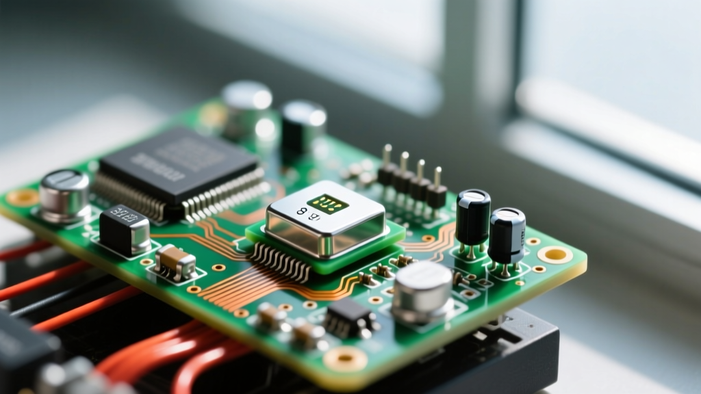

A crystal oscillator is an electronic circuit that uses the mechanical resonance of a vibrating piezoelectric crystal to generate a highly stable, precise electrical signal at a specific frequency. In a real circuit, swapping a drift-prone RC (resistor-capacitor) timer for a crystal oscillator changes everything: it replaces timing drift measured in percentage points with stability measured in parts-per-million (ppm), allowing microcontrollers to execute instructions synchronously, UART baud rates to match perfectly, and RF transceivers to lock onto exact channels without dropping packets.
The Core Principle: Piezoelectric Resonance
To understand the mechanics, look at the quartz crystal itself. Quartz exhibits the piezoelectric effect: when you apply mechanical stress to it, it generates a voltage. Conversely, the inverse piezoelectric effect means that when you apply an alternating voltage across the crystal's electrodes, it physically deforms and vibrates at its natural mechanical resonant frequency.
When placed in a feedback loop with an amplifier, the crystal acts as an incredibly sharp bandpass filter. The circuit naturally settles into oscillation at the exact frequency where the crystal's mechanical resonance occurs. The physical dimensions and cut of the quartz blank dictate this frequency. A thicker blank vibrates slower (lower frequency), while a thinner blank vibrates faster. For frequencies above ~30 MHz, manufacturers typically use overtone modes (vibrating at the 3rd or 5th harmonic) rather than cutting the quartz dangerously thin.
The Great Confusion: Bare Crystal vs. Active Oscillator Module
The most common mistake hobbyists and junior engineers make is conflating a crystal with an oscillator. They are not the same component, and putting the wrong one on your board will result in a dead circuit.
- The Bare Crystal (Passive): Usually a 2-pin or 4-pin SMD component (like the HC-49U through-hole can or a tiny 3.2x2.5mm ceramic SMD). It is just the quartz resonator. It cannot oscillate on its own. It requires an external sustaining amplifier—usually built into your microcontroller (like the ATmega328P or ESP32)—and external load capacitors to function.
- The Oscillator Module (Active): A 4-pin or 6-pin IC that contains the quartz crystal, the sustaining amplifier, and output buffering circuitry all in one package. You supply VCC and GND, and it outputs a clean, ready-to-use CMOS or LVDS square wave directly to your microcontroller's clock input pin. No load capacitors required.
XTAL1 and XTAL2 pins, you need a passive bare crystal. If it specifies a single CLKIN pin, you need an active oscillator module.
Worked Numeric Example: Sizing Load Capacitors
When using a passive bare crystal, you must provide load capacitors ($C_1$ and $C_2$) to ground. If you guess these values, your oscillator will run, but it will be off-frequency. If the crystal's datasheet specifies a Load Capacitance ($C_L$) of 18 pF, you do not just drop in 18 pF capacitors.
The formula for load capacitance is:
C_L = (C_1 * C_2) / (C_1 + C_2) + C_s
Where $C_s$ is the stray parasitic capacitance of your PCB traces and the microcontroller's internal pins. Let's walk through a real-world calculation.
The Scenario
- Crystal: 16.000 MHz AT-cut, specified $C_L$ = 18 pF.
- Stray Capacitance ($C_s$): ~5 pF (a safe, conservative estimate for standard FR4 PCB traces and modern CMOS MCU pins).
- Assumption: We will use equal value capacitors for $C_1$ and $C_2$ to maintain symmetry and reduce EMI.
The Calculation
Since $C_1 = C_2 = C$, the formula simplifies to:
C_L = (C / 2) + C_s
Plug in our known values:
18 pF = (C / 2) + 5 pF
13 pF = C / 2
C = 26 pF
The exact mathematical value is 26 pF. Looking at the standard E12 capacitor series, the nearest available value is 27 pF. Therefore, you will place two 27 pF capacitors from each crystal pin to ground.
Where You Meet This in Practice
Timing sources dictate the reliability of almost every digital system. Here is where you will encounter them on the bench:
- Microcontroller System Clocks: An ESP32-WROOM-32 module uses a 40 MHz bare crystal to drive its main CPU and WiFi MAC. If the PCB layout introduces too much stray capacitance or the crystal is placed too far from the pins, the WiFi radio will fail to calibrate, resulting in dropped connections.
- Real-Time Clocks (RTCs): Battery-backed RTCs rely on a 32.768 kHz tuning-fork crystal. Because $2^{15} = 32,768$, a simple 15-stage binary divider chain yields exactly one pulse per second. These tuning forks are highly sensitive to mechanical shock and ultrasonic cleaning processes, which can permanently alter their frequency or shatter the quartz.
- RF Synthesizers: In LoRa or Zigbee transceivers, the reference crystal is multiplied by a PLL to generate the 2.4 GHz or 915 MHz carrier. A cheap crystal with ±50 ppm tolerance can shift the carrier frequency enough to push it outside the receiver's narrow bandwidth, completely killing your link budget.
Decision Tree: Specifying Your Timing Source
Choosing between a bare crystal, an active quartz oscillator, and a modern MEMS oscillator depends on your environmental constraints, budget, and board space. Use this decision matrix to select your component.
| Design Constraint | If your priority is... | Then specify... |
|---|---|---|
| Ultra-low cost & high volume | Minimizing BOM cost below $0.30 per unit | Bare passive crystal + 2x C0G load caps |
| Low-frequency timekeeping | Keeping time while the main MCU sleeps | 32.768 kHz cylindrical tuning fork crystal |
| Fast startup & low voltage | Waking from deep sleep in < 1ms at 1.8V | Active CMOS Quartz Oscillator (4-pin) |
| Harsh environments & vibration | Operating in high-G vibration or -40°C to 85°C | MEMS Oscillator (e.g., SiTime MEMS) |
The Default Recommendation for Robust Prototyping
If you are designing a new mixed-signal board, operating in an environment with moderate EMI, and want to eliminate the headache of calculating load capacitance, routing symmetrical trace lengths, and debugging startup failures, skip the bare crystal.
Concrete Pick: Specify the ECS-2520MV-160-BN. This is a 16.000 MHz active CMOS oscillator in a tiny 2.5 x 2.0 mm package. It operates from 1.8V to 3.3V, requires only a 0.1 µF bypass capacitor, and outputs a clean square wave with a fast startup time. It costs roughly $1.20 in single quantities from suppliers like DigiKey, a small price to pay to guarantee your clock network works on the first PCB spin.
Frequently Asked Questions
Can I just use the microcontroller's internal RC oscillator instead of a crystal?
Yes, for simple tasks like blinking LEDs or reading slow analog sensors. However, internal RC oscillators typically have a tolerance of ±1% to ±3% (10,000 to 30,000 ppm). If you attempt to run UART at 115,200 baud or use USB/Bluetooth with an internal RC oscillator, the timing drift will cause framing errors and dropped connections. Always use a crystal for serial communications.
Why does my bare crystal fail to start oscillating when I power on the board?
Startup failure is usually caused by insufficient loop gain or excessive load capacitance. Check your PCB layout: the traces from the MCU's XTAL pins to the crystal must be as short as possible (under 5mm) and surrounded by a ground pour to shield them. If the traces are too long, the parasitic capacitance increases, lowering the loop gain below the threshold required to kickstart the mechanical vibration.
Are MEMS oscillators replacing quartz?
MEMS (Micro-Electromechanical Systems) oscillators are rapidly capturing market share in automotive, industrial, and telecom applications because they are immune to the mechanical shock that shatters quartz. However, for ultra-low-power applications (like a 32.768 kHz RTC drawing under 1 µA) and ultra-low phase noise RF applications, quartz still holds a distinct physics advantage.


