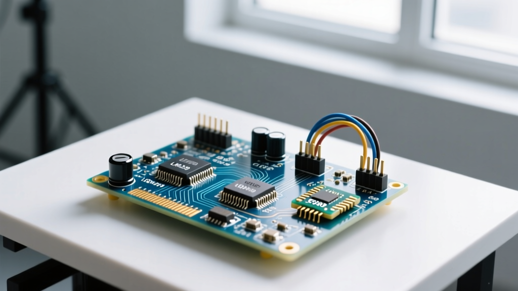
Electrical engineering encompasses the distinct but overlapping disciplines of power generation, solid-state electronics, control systems, signal processing, and telecommunications used to harness electromagnetism for practical applications. Understanding the boundaries between these areas in electrical engineering dictates which physical laws, component tolerances, and safety codes govern your specific project. When you design a circuit, you are rarely operating in just one domain; you are managing the friction between them. The most common and dangerous confusion occurs when builders conflate 'electronics' (low-voltage signal and control logic) with 'electrical' (high-voltage power distribution and heavy motors), leading to disastrous grounding mistakes, inadequate galvanic isolation, or melted traces.
The Core Domains: Where Physics Meets the Breadboard
While universities separate these fields into distinct degree tracks, the physical reality on your workbench forces them to interact. According to the U.S. Bureau of Labor Statistics, the profession is broadly categorized into power generation, electronic component design, and control systems, but practical application requires a more granular view.
- Power Engineering: Deals with the generation, transmission, and distribution of electrical energy. On the bench, this means sizing AWG wire for ampacity, calculating voltage drop across long feeders, and managing the thermal limits of high-current busbars. The governing physics here are macroscopic electromagnetism and thermodynamics.
- Electronics (Solid-State & Micro): Focuses on controlling electron flow through semiconductors to process signals or switch loads. This is your ESP32 GPIO pins, MOSFET gate drivers, and operational amplifiers. The governing physics involve quantum mechanics (bandgaps) and microscopic charge carrier mobility.
- Control Systems: The mathematical bridge that uses electronics to command power. This involves feedback loops, PID tuning, and sensor integration. If your power stage is the muscle, control systems are the nervous system.
- Signal Processing & Telecommunications: Concerned with extracting, filtering, and transmitting data from noisy environments. In a DIY context, this means designing RC low-pass filters to clean up a noisy current shunt reading before it hits your microcontroller's ADC.
Where You Meet This in Practice: The Intersecting Boundaries
You rarely build a project that stays neatly inside one silo. A smart motor controller, for example, is a collision of all four domains. The All About Circuits textbook series emphasizes that mastering the transitions between these domains is where most engineering failures occur. Here is how these areas in electrical engineering map to real bench tasks.
| Domain | Governing Law / Standard | Typical Component | Primary Hazard if Ignored |
|---|---|---|---|
| Power | Ohm's Law, NEC Article 310 | Contactors, Busbars, THHN Wire | Arc flash, insulation melt, fire |
| Electronics | Shockley Diode Equation | MOSFETs, Op-Amps, Microcontrollers | Silicon thermal runaway, magic smoke |
| Control | Nyquist Stability Criterion | Encoders, Hall Sensors, PID Loops | Oscillation, mechanical runaway |
| Signal Processing | Nyquist-Shannon Sampling Theorem | LC Filters, Ferrite Beads, ADCs | Aliasing, false triggering, noise |
Worked Numeric Example: Bridging Electronics and Power
Let’s look at a classic intersection: using a low-voltage electronic signal to switch a high-current electrical load. Suppose you are using an ESP32 (Electronics/Control) to drive a 12V, 15A DC windshield wiper motor (Power) via an IRFB4110 N-channel MOSFET.
The Setup: The ESP32 outputs a 3.3V PWM signal to a gate driver, which boosts it to 10V to fully enhance the MOSFET gate. The motor draws a continuous 15A under load.
The Calculation: We need to prove the MOSFET won't melt. We check the datasheet for the Drain-to-Source On-Resistance, $R_{DS(on)}$. At $V_{GS} = 10V$, the IRFB4110 has an $R_{DS(on)}$ of roughly 4.5 m\Omega (0.0045 $\Omega$).
Power dissipated as heat in the silicon is calculated using $P = I^2R$:
$P = (15A)^2 \times 0.0045 \Omega = 225 \times 0.0045 = 1.01 Watts$
Now we cross into thermodynamics. The junction-to-ambient thermal resistance ($\theta_{JA}$) for a standard TO-220 package in free air is roughly 62°C/W.
Temperature rise = $1.01W \times 62°C/W = 62.6°C$.
If your workshop ambient temperature is 25°C, the silicon junction will sit at 87.6°C. This is below the 175°C maximum rating, meaning it will survive. However, it is hot enough to burn your finger and leaves very little thermal headroom for the motor's startup stall current (which can spike to 40A). The practical fix is to bolt the TO-220 to a small extruded aluminum heatsink with thermal paste, dropping the thermal resistance to roughly 15°C/W and keeping the junction at a safe 40°C.
Real-World Scenario Walkthrough: When Domains Collide and Fail
Theory is clean; the workbench is messy. Here is a scenario where ignoring the boundary between signal processing and power engineering resulted in a catastrophic failure.
The Setup: A DIY 48V LiFePO4 solar inverter build. The builder designed a custom MPPT charge controller (Signal Processing/Control) on a 4-layer PCB, powered directly from the main 48V DC bus using a cheap, non-isolated LM2596 buck converter module. The control board generated high-frequency PWM signals to drive the inverter's H-bridge MOSFETs (Power).
The Numbers: The DC bus sat at 52V nominal. The inverter switched at 20 kHz, pulling peak currents of 60A through the main busbars. The control logic required a clean 5V rail drawing only 150mA.
The Outcome: Upon applying a heavy AC load, the inverter's microcontroller instantly hard-faulted, and the low-side MOSFETs in the H-bridge shorted out, venting magic smoke and tripping the main 100A DC breaker.
What Went Wrong: The failure occurred at the intersection of power and signal domains. When the H-bridge switched 60A at 20 kHz, the parasitic inductance of the physical busbars created massive voltage spikes ($V = L \frac{di}{dt}$). Because the builder used a non-isolated buck converter, the control board's logic ground was physically tied to the noisy, high-current power ground. The switching noise coupled directly into the microcontroller's ground plane, causing a brownout that corrupted the PWM dead-time registers. With the dead-time corrupted, both high-side and low-side MOSFETs turned on simultaneously (shoot-through), creating a dead short across the 52V battery bank.
The Fix: The power domain must be galvanically isolated from the signal domain. The builder replaced the cheap buck converter with an isolated DC-DC converter (like a RECOM ROE-0505S) to power the logic, and used digital isolators (like the Si8662) on the PWM lines. The logic ground was now entirely floating relative to the power ground, rendering the $di/dt$ noise invisible to the microcontroller.
Frequently Asked Questions
Do I need to understand telecommunications to build RF remote controls for my home automation?
Yes, but only at the applied level. You don't need to derive Maxwell's equations, but you must understand impedance matching, antenna tuning, and the difference between ground-wave and line-of-sight propagation. Treating an RF module like a standard DC electronics component (ignoring the telecom/RF domain) will result in severe range degradation due to standing waves and mismatched traces.
Why do control systems engineers care about power engineering?
Because a control loop is only as fast as the physical actuator it commands. If you tune a PID loop for a servo motor without understanding the motor's electrical time constant and the power supply's current limits, your mathematically perfect control signal will just cause the power supply to brownout or the motor to overheat.
Which area in electrical engineering is most critical for home DIY wiring?
Power engineering, specifically the sub-discipline of power distribution and safety. You must understand ampacity, thermal derating, fault-current paths, and equipotential bonding. Signal processing and telecommunications are virtually irrelevant when sizing a subpanel feeder or wiring a 3-way switch.