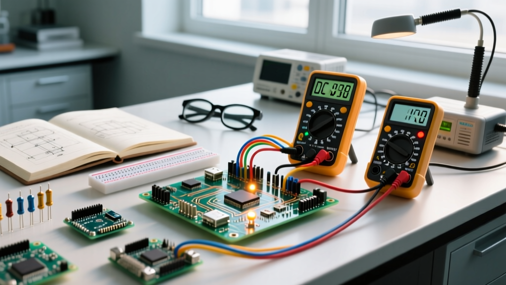
A crystal clock oscillator is an active, self-contained electronic circuit that uses the mechanical resonance of a vibrating quartz crystal to generate a precise, continuous square-wave output signal. By dropping one of these onto your PCB, you replace a microcontroller's sloppy, temperature-drifting internal RC oscillator with a rock-solid timing baseline, which is the absolute minimum requirement for high-speed UART, USB, or RF communication to function without dropping packets.
The most common mistake hobbyists and junior engineers make is confusing a passive quartz crystal (a 2-pin or 4-metal-pad resonator that requires external load capacitors and relies on the MCU's internal Pierce oscillator circuit to start vibrating) with an active crystal clock oscillator (a 4-pin or 6-pin complete module with an internal sustaining amplifier that outputs a ready-to-use, logic-level clock signal). Passive crystals cost around $0.20 but demand careful PCB layout; active oscillators cost $0.80 to $1.50 but guarantee startup and clean logic transitions.
The Math That Matters: PPM, Drift, and Baud Rates
Timing accuracy is measured in Parts Per Million (PPM). To understand what this changes in a real circuit, let's run a numeric example using a standard 16 MHz clock with a stability rating of ±20 PPM.
- Max Frequency Error: 16,000,000 Hz × (20 / 1,000,000) = 320 Hz.
- Actual Clock Range: 15,999,680 Hz to 16,000,320 Hz.
- Percentage Error: 20 PPM = 0.002%.
Now, apply this to a 115,200 baud UART link. The UART hardware generates its baud rate by dividing the main clock. If the main clock drifts by 0.002%, the baud rate drifts by exactly 0.002%. Standard UART receivers tolerate up to ±2% total timing error (including both transmitter and receiver drift). At 0.002%, your 20 PPM crystal is well within the safe zone.
Contrast this with an internal MCU RC oscillator rated at ±1% (10,000 PPM). If both your transmitter and receiver use internal RC oscillators, your worst-case combined drift is 2%. You are now right on the edge of UART framing errors, and you will completely fail USB communication, which mandates a maximum drift of ±50 PPM (0.005%).
Where You Meet This in Practice
You will encounter strict clock oscillator requirements the moment your project leaves standalone GPIO blinking and starts talking to the outside world at high speeds.
- Wi-Fi and Bluetooth (ESP32/nRF52): RF carrier synthesis requires exact frequencies. An ESP32-WROOM-32 module, for instance, integrates a 40 MHz passive crystal. If you are designing a custom board around a bare ESP32-S3 chip, you must provide a 40 MHz clock with tight PPM, or the radio will fail to calibrate and drop connections.
- USB Interfaces: Native USB on STM32 or RP2040 chips, or external bridges like the FT232 and CH340, require 48 MHz or 8 MHz clocks. USB eye-diagram compliance strictly enforces the ±50 PPM limit. If you try to run a USB stack off an internal RC oscillator, the host PC will reject the device enumeration.
- Digital Audio (I2S): If you are driving a DAC for audio playback, you need specific non-integer frequencies like 22.5792 MHz or 24.576 MHz to perfectly divide down to 44.1 kHz or 48 kHz sample rates without introducing audible aliasing or jitter.
Active Oscillator vs. Passive Crystal: The Decision Path
Choosing between a passive resonator and an active oscillator dictates your BOM cost, your PCB layer count, and your layout headaches. Use the decision tree below to select the right architecture for your board.
| Design Constraint / Scenario | Recommended Component Type | Why This Wins |
|---|---|---|
| High-volume consumer toy, extreme BOM cost pressure, 2-layer PCB | Passive Quartz Crystal (e.g., ECS-160-20-33) | Saves $0.60 per unit; internal MCU Pierce gate handles oscillation. |
| USB, Ethernet, or RF compliance required; 4-layer PCB available | Active Quartz Oscillator (e.g., ECS-2520 series) | Guarantees startup, outputs clean CMOS levels, eliminates load-cap tuning. |
| Harsh industrial environment (-40°C to +85°C), high vibration | Active MEMS Oscillator (e.g., SiTime SiT8008) | MEMS resonators are immune to mechanical shock and have superior temp stability. |
| Battery-powered sleep node needing 32.768 kHz RTC timing | Passive Tuning Fork Crystal (e.g., Seiko SSC-12T) | Active 32kHz oscillators draw too much quiescent current for deep sleep. |
Common Failure Modes and Layout Mistakes
Even when you select the correct part, poor PCB layout will destroy your signal integrity. Here are the failure modes that actually happen on the bench:
- Parasitic Capacitance Killing Passive Startup: If you use a passive crystal, the traces from the MCU pins to the crystal must be as short as physically possible (under 5mm). Long traces add parasitic capacitance, which shifts the resonant frequency and prevents the internal amplifier from gaining enough loop gain to start oscillating. Fix: Keep traces short, and pour a ground plane directly underneath the crystal to shield it from noise.
- Active Oscillator Ringing and EMI: An active oscillator outputs a very fast, high-current CMOS square wave. If you route this directly into a high-impedance MCU input or a long trace, the fast edges will ring, causing electromagnetic interference (EMI) and potentially double-clocking the MCU. Fix: Place a 22Ω to 33Ω series damping resistor directly on the output pin of the active oscillator, as close to the package as possible.
- Voltage Mismatch Bricking the Input Buffer: Many modern active oscillators are available in 1.8V, 2.5V, and 3.3V variants. If you accidentally solder a 1.8V oscillator (like the ECS-2520S18) into a 3.3V system, the 3.3V logic high from the oscillator will exceed the absolute maximum ratings of a 1.8V-tolerant MCU input, or conversely, a 3.3V oscillator might not trigger the threshold of a 1.2V core logic pin. Fix: Always verify the VDD pin requirement on the oscillator datasheet against your local power rail.
For deeper layout guidelines, refer to the crystal selection and layout guides on All About Circuits, or review the oscillator theory primers on Electronics Tutorials. If you are evaluating MEMS alternatives for harsh environments, the MEMS vs. Quartz comparison data from SiTime provides excellent benchmark graphs on phase noise and shock resistance.
Frequently Asked Questions
Can I use a 5V crystal oscillator on a 3.3V microcontroller?
No, not directly. A 5V active oscillator will output a 5V logic high, which will fry the GPIO pin of a 3.3V microcontroller. You must either use a level shifter, a voltage divider, or simply buy the 3.3V variant of the exact same oscillator family.
Why does my passive crystal only start oscillating when I touch it with a multimeter probe?
This is a classic sign of insufficient loop gain or incorrect load capacitance. Your multimeter probe adds a few picofarads of parasitic capacitance to the circuit, which accidentally pushes the phase shift just enough to kickstart the oscillation. Recalculate your load capacitors ($C_L$) using the formula $C_L = (C1 imes C2) / (C1 + C2) + C_{stray}$.
Do MEMS oscillators sound or act like quartz?
Electrically, yes. A MEMS oscillator like the SiT8008 has the exact same 4-pin footprint and output logic levels as a quartz active oscillator. Internally, it uses a microscopic silicon resonator instead of a cut quartz blank, making it vastly superior in high-vibration environments like motor controllers or drones.