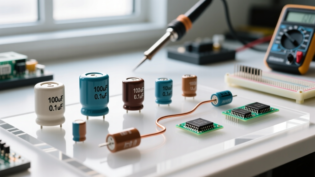

When you look at a schematic, the capacitor uF definition is straightforward: a microfarad (µF) is one-millionth of a Farad (10-6 F), representing the ability to store one microcoulomb of charge per volt. But on the workbench, that theoretical number is often a lie. A 10µF ceramic capacitor might only give you 4µF under real DC bias. This guide moves past the textbook capacitor uF definition to show you how to decode physical markings, navigate dielectric derating, and safely substitute parts when your exact BOM item is out of stock.
1 µF = 0.000001 Farads = 1,000 nF (nanofarads) = 1,000,000 pF (picofarads)
Decoding Physical Markings and the 3-Digit Code
Through-hole electrolytic capacitors are easy; they print the value and voltage directly on the sleeve (e.g., "10µF 50V"). But when you are working with surface-mount device (SMD) multilayer ceramic capacitors (MLCCs) or small film caps, you will run into the EIA 3-digit marking system. Misreading this code is the most common reason hobbyists order the wrong parts.
The first two digits are the significant figures, and the third digit is the multiplier (number of zeros), always in picofarads (pF). You then convert back to µF.
- Code 104: 10 × 104 pF = 100,000 pF = 100 nF = 0.1 µF (The most common bypass cap in existence).
- Code 475: 47 × 105 pF = 4,700,000 pF = 4,700 nF = 4.7 µF.
- Code 226: 22 × 106 pF = 22,000,000 pF = 22 µF.
Following the numbers, you will often see a letter indicating tolerance. J means ±5%, K means ±10%, and M means ±20%. If you are designing a 555 timer oscillator or an active filter, you need J or K tolerance. For power rail decoupling, M (±20%) is perfectly acceptable.
Dielectric Types: Which Capacitor for Which Job?
Knowing the capacitor uF definition is useless if you pick the wrong dielectric. A 10µF aluminum electrolytic and a 10µF MLCC behave entirely differently at high frequencies. Here is the selection matrix we use on the bench.
| Type / Dielectric | Construction | Typical Tolerance | Tempco / Stability | Typical Use Case |
|---|---|---|---|---|
| MLCC (C0G/NP0) | Ceramic (Class I) | ±1% to ±5% | 0 ±30 ppm/°C (Ultra-stable) | RF filters, oscillator tanks, precision timing |
| MLCC (X7R/X5R) | Ceramic (Class II) | ±10% to ±20% | ±15% over temp (Moderate) | General decoupling, bulk bypass, SMPS output |
| Aluminum Electrolytic | Foil + Liquid Electrolyte | ±20% | Poor (High temp drift, dries out) | High-capacitance bulk storage, audio coupling |
| Polymer Tantalum | Sintered Tantalum + Polymer | ±10% to ±20% | Good (Low ESR, stable) | Space-constrained bulk decoupling on low-V rails |
| Film (Polypropylene) | Metallized Plastic Film | ±1% to ±5% | Excellent (Self-healing) | AC line filtering, snubber circuits, high voltage |
The Bench Scenario: When a 10µF MLCC Caused a Brownout
Let us look at a real failure that highlights why the theoretical capacitor uF definition falls apart in practice.
The Setup: We were designing a custom carrier board for an ESP32-S3 module. The 3.3V power rail needed bulk decoupling to handle WiFi transmission current spikes, which can hit 350mA for a few milliseconds. The schematic called for a 10µF capacitor near the module's VDD pin.
The Numbers: To save board space, we selected a Murata GRM21BR60J106ME73—a 10µF, 6.3V, X5R MLCC in a tiny 0805 package. On paper, 10µF is plenty to bridge a 2ms current spike without the voltage drooping below the ESP32's 2.7V brownout threshold.
The Outcome: During RF certification testing, the ESP32 kept resetting randomly. Hooking up an oscilloscope to the 3.3V rail revealed the voltage was dipping to 2.4V during WiFi TX bursts.
What Went Wrong: We ignored DC bias derating. At 3.3V applied, we were operating at 52% of the capacitor's 6.3V rated voltage. At this bias point, the X5R dielectric loses roughly 50% of its capacitance. Our "10µF" capacitor was physically acting as a 5µF capacitor. Furthermore, the 0805 package has higher Equivalent Series Inductance (ESL) than smaller packages, choking off high-frequency transient response.
The Fix: We replaced the single 0805 part with two parallel 4.7µF, 10V X7R caps in 0603 packages (lower ESL, less severe derating at 3.3V), plus a 22µF polymer tantalum for true low-frequency bulk storage. The voltage dip shrank to 150mV, and the brownouts vanished.
Failure Modes and Visual Symptoms on the PCB
Capacitors fail in distinct ways depending on their chemistry. When troubleshooting a dead board, look for these specific visual and measured symptoms, as detailed in standard component failure guides.
- Aluminum Electrolytic (Drying / Venting):
- Visual: The top cross-vent is bulged upward, or there is a crusty brown residue leaking from the bottom rubber seal.
- Measured: Capacitance drops massively, and Equivalent Series Resistance (ESR) spikes. An ESR meter will read >5Ω on a cap that should be <0.5Ω.
- MLCC (Flex Cracking):
- Visual: Often invisible to the naked eye. If the board was bent during depanelization or connector insertion, a hairline crack forms diagonally from the pad edge inward. In severe short-circuit failures, the capacitor body blows apart, leaving a charred crater.
- Measured: Reads as a dead short (0Ω) across the rail with a multimeter.
- Tantalum (Thermal Runaway):
- Visual: A distinct charred black mark on the board. Tantalum capacitors fail violently if reverse-biased or hit with a high-voltage spike. They often smell like burnt sugar or ozone.
- Measured: Dead short. The part is physically destroyed.
Safe Substitution Rules When the Exact Part is Missing
When you are prototyping at 2 AM and the exact BOM part is out of stock at DigiKey, you need to know what you can safely swap. Use this decision framework to avoid blowing up your prototype.
1. Can I use a higher voltage rating?
Yes, almost always. Swapping a 16V rated cap for a 25V rated cap of the same uF value is electrically safer. However, watch the physical size. A 25V 10µF MLCC might require a 1206 case instead of an 0805. The larger case size increases parasitic ESL, which can ruin high-frequency decoupling. For bulk storage, size does not matter; for high-speed IC decoupling, stick to the original case size.
2. Can I use a higher capacitance value?
It depends on the circuit function. If the capacitor is used for bulk decoupling or power filtering, going from 10µF to 22µF is fine and often beneficial. If the capacitor is part of a timing circuit, oscillator, or active filter (like a Sallen-Key topology), changing the uF value changes the RC time constant or the cutoff frequency. Never substitute capacitance values in timing circuits without recalculating the resistor values.
3. Can I swap dielectric types?
Proceed with extreme caution.
- Never swap C0G for X7R in audio paths or filters. X7R ceramics exhibit the piezoelectric effect (microphonics)—they act like microphones and inject mechanical vibration noise into your signal as electrical noise. C0G does not.
- Never swap an electrolytic for an MLCC in high-ripple SMPS outputs without checking the RMS ripple current rating. MLCCs have no published ripple current limits because they do not have liquid electrolyte to boil, but the PCB traces and vias might overheat if the ESR is too low and ringing occurs.
- Never replace a polymer tantalum with a standard MnO2 tantalum in circuits with high inrush current. Standard tantalums require heavy voltage derating (often 50%) to survive turn-on surges without catching fire.
Understanding the capacitor uF definition is just the starting line. True bench expertise comes from knowing how that microfarad value shifts under voltage, temperature, and mechanical stress—and knowing exactly which part to grab from your component bins when the schematic meets reality.


