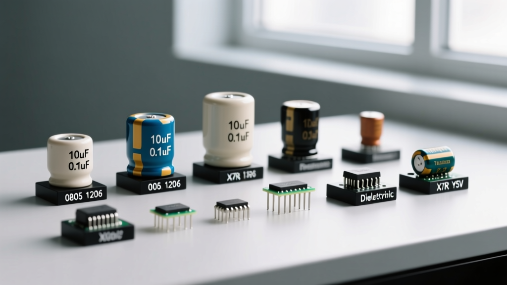

When an engineer or hobbyist says they need a '100nF capacitor,' they have only solved half the problem. The term capacitor size actually refers to two distinct parameters: the electrical size (capacitance and voltage rating) and the physical size (the case footprint and 3D dimensions). Buying the right part means balancing electrical requirements against parasitic effects, PCB real estate, and the harsh realities of DC bias derating.
The direct answer for sizing any capacitor is this: always select a voltage rating at least 2x your maximum operating voltage to account for DC bias derating in ceramics and surge safety in tantalums, and choose the smallest physical SMD case that meets your capacitance needs to minimize parasitic equivalent series inductance (ESL). Below is the complete framework for translating a schematic symbol into a physical part number.
Decoding Capacitor Size: Electrical Value vs. Physical Footprint
Physical capacitor size is standardized by the Electronics Industries Alliance (EIA) for surface mount devices (SMD) and by diameter/length for through-hole radial parts. In high-frequency digital circuits, physical size dictates parasitic inductance. A smaller physical loop area between the capacitor's internal plates and the PCB pads results in lower ESL, making smaller capacitors inherently better at filtering high-frequency noise.
However, you cannot simply shrink the footprint to save space. Physical volume limits the maximum capacitance you can achieve for a given dielectric and voltage rating. Furthermore, Class II ceramic dielectrics (like X7R and X5R) suffer from severe DC bias derating. A 10µF 0805 X5R capacitor rated for 16V might only deliver 2.5µF of actual capacitance when biased at 12V. You must use manufacturer tools like Murata's SimSurfing to verify the effective capacitance under your actual DC operating voltage.
| EIA Code | Imperial | Metric (mm) | Max Cap (X7R 16V approx) | Typical ESL (nH) | Best Application |
|---|---|---|---|---|---|
| 0201 | 0201 | 0603 | 100nF | ~0.4 nH | High-density mobile RF, ultra-low ESL decoupling |
| 0402 | 0402 | 1005 | 470nF | ~0.5 nH | Standard logic IC decoupling, general purpose |
| 0603 | 0603 | 1608 | 2.2µF | ~0.7 nH | Power rail bulk decoupling, audio coupling |
| 0805 | 0805 | 2012 | 10µF | ~1.0 nH | Input/Output filtering, moderate energy storage |
| 1206 | 1206 | 3216 | 47µF | ~1.5 nH | High-voltage snubbers, large bulk bypass |
| 1210 | 1210 | 3225 | 100µF | ~1.8 nH | Replacing electrolytics in low-profile designs |
Dielectric Selection: Which Type for Which Job?
Choosing the correct capacitor size also means choosing the right internal chemistry. The dielectric material determines the temperature coefficient (tempco), microphonics, equivalent series resistance (ESR), and lifespan. Using a Y5V ceramic where a C0G is required will cause your filter's cutoff frequency to drift wildly as the board warms up.
| Dielectric / Type | Construction | Tolerance | Tempco / Temp Range | Typical Use Case |
|---|---|---|---|---|
| C0G / NP0 | Class I Ceramic | ±5% or better | 0 ±30ppm/°C (-55 to 125°C) | RF matching, precision filters, oscillator timing |
| X7R / X5R | Class II Ceramic | ±15% to ±20% | ±15% (-55 to 125°C / 85°C) | General decoupling, bypass, non-critical coupling |
| Aluminum Electrolytic | Wound Foil / Liquid | ±20% typical | High capacitance drift (-40 to 105°C) | Bulk power storage, low-frequency ripple filtering |
| Solid Tantalum | Sintered Pellet / MnO2 | ±10% to ±20% | Stable but high temp derating (-55 to 125°C) | Space-constrained bulk decoupling, medical/aero |
| Polypropylene (Film) | Metallized Plastic Film | ±1% to ±5% | Very stable, self-healing (-55 to 105°C) | AC line filtering, high-current snubbers, audio crossovers |
Selection Criteria: Always use C0G/NP0 for any circuit where the capacitor sets a frequency or timing threshold. Use X7R for digital power decoupling. Use Aluminum Electrolytic when you need hundreds of microfarads at a low cost, but be aware of their high ESR and limited lifespan (often rated for only 2,000 to 10,000 hours at max temperature). Use Polypropylene film capacitors for any application involving high AC ripple currents or direct mains voltage connection.
Reading the Markings: SMD Codes and Radial Print
Physical capacitor size often limits the space available for printing, leading to cryptic marking schemes. Misreading these codes is a primary cause of bench failures.
SMD Ceramic 3-Digit Codes
Most 0603 and larger ceramic capacitors use a three-digit EIA code. The first two digits are the significant figures, and the third digit is the multiplier (number of zeros), expressed in picofarads (pF).
- 104: 10 × 10^4 pF = 100,000 pF = 100nF = 0.1µF
- 473: 47 × 10^3 pF = 47,000 pF = 47nF
- 221: 22 × 10^1 pF = 220 pF
Polarity Stripes: The Tantalum Trap
This is a critical safety distinction. On an aluminum electrolytic capacitor, the printed stripe with minus signs indicates the NEGATIVE cathode. On a solid tantalum capacitor, the printed band indicates the POSITIVE anode. Reversing an electrolytic will cause it to vent; reversing a tantalum will cause it to ignite and short-circuit the power rail.
Through-Hole Letter Codes
Radial film and ceramic capacitors often append a letter to denote tolerance. 'J' means ±5%, 'K' means ±10%, and 'M' means ±20%. A marking reading '104K' is a 100nF capacitor with a 10% tolerance.
Substitution Rules and Failure Modes
When the exact BOM part is out of stock, you must substitute safely. The golden rule of capacitor substitution is: Capacitance can go up (within reason), Voltage rating MUST go up or stay the same, and ESR should go down or stay the same.
Safe Substitutions:
- Replacing a 16V X7R with a 25V X7R of the same physical size (improves DC bias performance).
- Replacing a 10µF Aluminum Electrolytic with a 10µF or 22µF Low-ESR Polymer capacitor (improves ripple handling).
- Replacing an X5R with an X7R (widens the operating temperature range).
Unsafe Substitutions:
- Replacing a C0G with an X7R in an LC filter (will cause severe frequency drift and microphonic noise).
- Replacing a 10V rated part with a 6.3V part to save space (will lead to catastrophic dielectric breakdown).
- Replacing a standard electrolytic with a Tantalum without verifying the circuit's inrush current (tantalums fail short under high surge currents).
Visual Failure Modes
When debugging a dead board, inspect capacitors for these specific physical symptoms:
- MLCC Flex Cracking: Often invisible to the naked eye. Caused by PCB bending during depaneling or connector insertion. Results in a dead short. Look for hairline fractures near the solder fillets using a 10x loupe.
- Electrolytic Venting: The aluminum can bulges at the scored cross on top, or leaks a brown, crusty residue. Smells distinctly fishy. Caused by overvoltage, reverse polarity, or end-of-life drying out.
- Tantalum Thermal Runaway: Leaves a blackened, charred crater on the PCB. Caused by reverse polarity, excessive voltage spikes, or high ripple current exceeding the part's thermal dissipation limits.
Practical Sizing Workflow for PCB and Breadboard Designs
To finalize your capacitor size selection on your next design, follow this sequential workflow to prevent respins and bench failures:
- Define the Electrical Need: Calculate the required capacitance for your specific function (e.g., 22µF for a buck converter output filter to meet ripple specs).
- Apply Voltage Derating: If your rail is 12V, select a minimum 25V rating for ceramics to counteract DC bias loss, or a 16V/20V rating for low-ESR polymers.
- Check Physical Constraints: Select the smallest EIA footprint that meets the derated capacitance. If a 1206 is required for 22µF at 25V, ensure your PCB layout has the clearance.
- Verify Parasitics: For high-speed digital rails (like DDR4 memory or FPGAs), parallel multiple smaller physical sizes (e.g., four 0402 100nF caps) instead of one large 1206 cap to minimize total ESL.
- Confirm Thermal and Ripple Limits: If using electrolytics or tantalums for bulk storage, calculate the RMS ripple current and verify it is below the manufacturer's maximum rating at your expected ambient temperature.
By treating capacitor size as a multi-variable optimization problem rather than a simple lookup table, you ensure circuit stability, longevity, and compliance with the physical realities of component parasitics.


