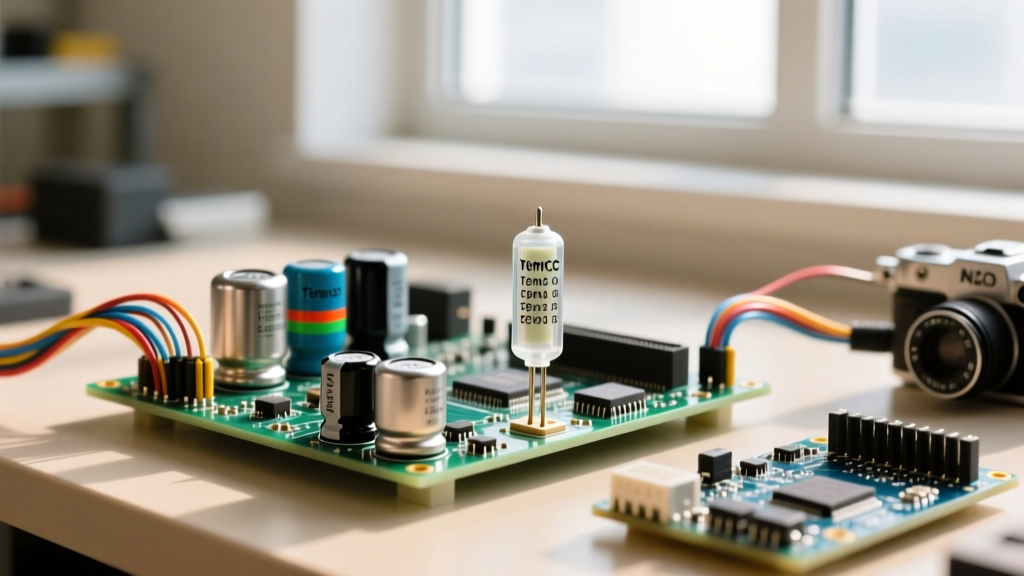

When you search for 'capacitor NTC,' you are usually trying to solve one of two distinct bench problems: selecting an NTC (Negative Temperature Coefficient) thermistor to limit inrush current when charging a large capacitor bank, or deciphering a ceramic capacitor's temperature coefficient (tempco) marking. Both involve 'NTC' physics, but they apply to completely different components. This guide gives you the exact formulas to size an inrush limiter for your power supply and the reference tables to decode capacitor tempco codes like X7R and C0G.
Decoding Capacitor Temperature Coefficients (Tempco)
Every ceramic capacitor changes capacitance as its temperature changes. Some exhibit a negative temperature coefficient (capacitance drops as it gets hotter), while others are virtually flat. The Electronics Industries Alliance (EIA) uses a three-character code to define this behavior. Understanding this code prevents catastrophic drift in precision analog circuits.
How to Read the EIA Tempco Marking
Take a standard multilayer ceramic capacitor (MLCC) marked X7R. Here is how to break down the three characters based on the Murata ceramic capacitor specifications:
- First Character (Minimum Temperature): 'X' means -55°C. (Other common letters: Y = -30°C, Z = +10°C).
- Second Character (Maximum Temperature): '7' means +125°C. (Other common numbers: 5 = +85°C, 6 = +105°C, 8 = +150°C).
- Third Character (Maximum Capacitance Change): 'R' means ±15% variation across that entire temperature range. (Other common letters: P = ±10%, V = +22% to -82%).
Capacitor Type Comparison Matrix
| EIA Code | Class / Construction | Tempco / Tolerance | Typical Use Case | Substitution Rule |
|---|---|---|---|---|
| C0G (NP0) | Class I / Para-electric | ±30ppm/°C (Stable) | RF filters, precision timing, snubbers | Can sub for X7R (costs more, larger footprint) |
| X7R | Class II / Ferroelectric | ±15% (-55 to +125°C) | General decoupling, bypass, bulk DC | Standard default; never sub Y5V for this |
| X5R | Class II / Ferroelectric | ±15% (-55 to +85°C) | Consumer electronics, battery devices | Can sub X7R if space allows (X7R handles more heat) |
| Y5V | Class III / High-K | +22% / -82% (-30 to +85°C) | Low-cost bulk storage (non-critical) | Never use in timing or feedback loops |
Sizing NTC Thermistors for Capacitor Inrush Limiting
When a discharged capacitor bank is connected to a DC or rectified AC source, it initially acts as a dead short. The inrush current is limited only by the parasitic resistance of the wiring and the ESR of the capacitors. Without an NTC inrush current limiter, this spike can weld relay contacts, blow upstream fuses, or trip AC breakers. For deeper theory on this phenomenon, refer to this All About Circuits primer on NTC thermistors.
An NTC thermistor (like the Ametherm SL series) has a high resistance when cold. As current flows, it self-heats, and its resistance drops dramatically, allowing normal steady-state operation with minimal voltage drop.
The 3-Step Sizing Formula
Let's size an NTC for a 120VAC mains supply feeding a bridge rectifier and a 4,700µF capacitor bank.
- Calculate Peak Voltage and Energy (Joules):
120VAC RMS = 170V Peak.
Energy ($E$) = $0.5 imes C imes V_{peak}^2$
$E = 0.5 imes 0.0047F imes (170V)^2 = 67.9 Joules.
Your NTC must have an energy rating higher than 68J to survive the initial charge without shattering. - Determine Cold Resistance ($R_{cold}$):
If your upstream breaker is rated for 15A, you want to limit inrush to roughly 30A-40A to prevent nuisance tripping.
$R_{cold} = V_{peak} / I_{inrush} = 170V / 34A = 5 Ohms. - Verify Steady-State Current:
If your load draws 3A continuous, ensure the NTC's maximum continuous current rating is at least 3A (preferably 5A for derating). At 3A, a 5Ω NTC will heat up and drop its resistance to roughly 0.2Ω, dissipating about 1.8W ($I^2R$).
Component Failure Modes and Visual Symptoms
Knowing how these components fail saves hours of troubleshooting. Here is what to look for when a board comes in dead.
NTC Thermistor Failures
- Shattered Epoxy / Split Body: Caused by exceeding the Joule rating. If a short circuit occurs downstream, the NTC absorbs massive energy trying to limit the fault current and literally explodes or cracks open.
- Thermal Runaway (Melted Solder/PCB): Occurs when the steady-state current exceeds the NTC's rating. It never cools down, stays at low resistance, but dissipates too much heat, scorching the PCB beneath it.
Capacitor Failures (Tempco Related)
- Microphonic Cracking (MLCCs): Class II (X7R) and Class III (Y5V) ceramics are piezoelectric. Board flex during assembly or operation can cause invisible micro-cracks. The cap fails as a dead short. Visually, you might see a tiny hairline fracture near the solder pad, but often you must probe it with a DMM to find the short.
- Electrolytic Venting: Not tempco-related, but common alongside NTCs. Look for a bulging scored top, or crusty brown/white electrolyte leaking from the bottom rubber bung.
The Decision Path: Which Type for Which Job?
Use this decision tree to terminate your part selection process. No more guessing.
| If your application is... | Then choose this Tempco / Component | Concrete Part Number Default |
|---|---|---|
| Precision analog filter, RC timing, or RF matching | C0G / NP0 Ceramic Capacitor | Kemet C0805C104J5GACTU (100nF, 50V, C0G) |
| General MCU decoupling, digital IC bypass, bulk DC | X7R Ceramic Capacitor | Murata GRM21BR71H105KA12L (1µF, 50V, X7R) |
| 120VAC Inrush limiting for < 5,000µF cap bank | NTC Thermistor (5Ω cold, >70J) | Ametherm SL32 5R009 (5Ω, 9A max, 85J) |
| 240VAC Inrush limiting for large motor drives / amps | NTC Thermistor (10Ω cold, >150J) | Ametherm SL32 10R015 (10Ω, 15A max, 250J) |
Safe Substitution Rules
When your exact BOM part is out of stock at DigiKey or Mouser, follow these substitution laws:
- Capacitors: You can always substitute a C0G for an X7R (it is an upgrade in stability, though it costs roughly 3x more and takes up more board space). Never substitute a Y5V for an X7R; your capacitance will drop by 80% on a hot summer day, causing brownouts.
- NTC Thermistors: You can safely substitute an NTC with a higher Joule rating or a higher maximum continuous current rating. You can substitute a slightly higher cold resistance (e.g., using a 10Ω instead of a 5Ω), which will halve your inrush current, but ensure your power supply can tolerate the slightly longer startup ramp time. Never substitute a lower Joule rating.
Concrete Bench Recommendations
If you are designing a standard 120VAC-to-DC bench power supply with a 4,700µF filter bank, stop calculating and order the Ametherm SL32 2R025. It has a 2Ω cold resistance, handles up to 25A steady-state, and absorbs 140 Joules. It costs about $2.85 in single quantities and will comfortably survive the 68J inrush spike of your capacitor bank while dropping to a negligible 0.08Ω during normal operation.
For the 100nF decoupling capacitors on your PCB, default to Murata's GRM series X7R unless you are building a precision ADC front-end, in which case spend the extra $0.04 per part and use Kemet's C-series C0G. Locking in these defaults eliminates 90% of passive component selection friction on the bench.


