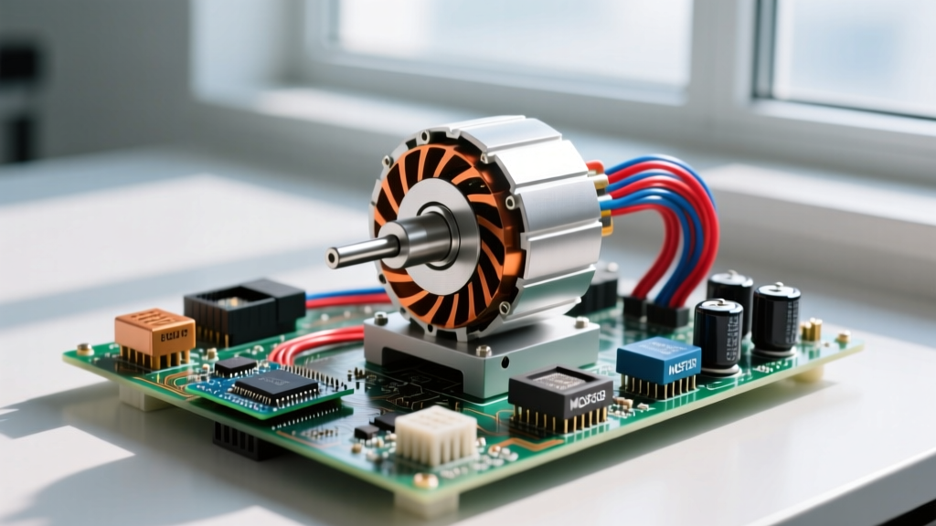

The BLDC motor working principle relies on electronic commutation rather than mechanical brushes. A permanent magnet rotor follows a rotating magnetic field generated by a 3-phase stator, controlled by a driver circuit that switches DC current through the windings in a precise sequence. This eliminates brush friction, reduces electromagnetic interference (EMI), and pushes efficiency into the 85–95% range. Whether you are building a robotic arm joint, a drone propulsion system, or an automated conveyor, understanding how to size, wire, and debug these motors is the difference between a smooth-running machine and a melted driver board.
The BLDC Motor Working Principle and Terminal Identification
At the bench, a Brushless DC (BLDC) motor looks like a simple 3-wire device, but the physics inside demand precise timing. The stator contains three sets of windings (Phases A, B, and C) arranged 120 electrical degrees apart. The rotor houses permanent magnets (usually NdFeB). To create continuous rotation, the driver must energize two phases at a time while leaving the third floating, stepping through a 6-state commutation sequence. This trapezoidal drive pushes current through the stator, pulling the permanent magnet rotor along.
For closed-loop commutation, the controller needs to know the exact angular position of the rotor. This is achieved via Hall-effect sensors embedded in the stator or by measuring the back-electromotive force (back-EMF) on the floating phase.
Wiring and Terminal Identification
When you strip back the sleeving on a typical NEMA-style or outrunner BLDC motor, you will find two distinct harnesses:
- Power Phases (U, V, W): These are the thick, heavy-gauge wires (often 12-18 AWG depending on current). They connect directly to the motor's stator windings. While they are technically interchangeable (swapping any two will reverse the motor's direction), standard convention maps U to Phase A, V to Phase B, and W to Phase C.
- Hall Sensor Harness: Typically a 5-pin JST-PH (2.0mm pitch) connector with 24-28 AWG wires. The pinout is strictly standardized on industrial motors: VCC (Red, 5V), GND (Black), Hall A (Yellow), Hall B (Green), and Hall C (Blue). Supplying these with 12V or 24V will instantly fry the internal silicon.
Motor Type Comparison: Matching the Load Profile
Choosing the right motor is about matching the torque curve to your mechanical load. A common mistake on the workbench is treating a NEMA stepper and a BLDC servo as interchangeable because they both accept step/direction or PWM inputs. They are fundamentally different beasts. Steppers excel at low-speed holding torque but suffer massive torque drop-off at high RPM due to winding inductance. BLDC motors maintain a flat torque curve up to their rated speed but require complex Field Oriented Control (FOC) algorithms to hold position at zero speed.
The table below breaks down the core electromechanical differences to help you select the right actuator for your specific load profile.
| Motor Type | Torque Curve Profile | Control Complexity & Needs | Relative Cost | Best Load Profile |
|---|---|---|---|---|
| BLDC (Trapezoidal) | Flat up to base speed, drops inversely with RPM beyond base speed. | Medium. Requires 6-step ESC or driver IC with Hall feedback. | Medium ($15–$60) | Continuous rotation, fans, pumps, RC propulsion, conveyors. |
| BLDC (FOC / Servo) | Flat continuous torque, high peak torque for acceleration. | High. Needs 3-phase shunt resistors, fast ADC, and FOC algorithm (e.g., SimpleFOC). | High ($50–$200+) | Robotic joints, CNC spindles, precision positioning, gimbals. |
| NEMA Stepper | Massive holding torque at 0 RPM; severe drop-off above 1000 RPM. | Low. Open-loop step/direction pulses. No position feedback required. | Low ($10–$30) | 3D printer axes, low-speed linear actuators, pick-and-place heads. |
| Brushed DC | Linear drop from stall torque to no-load speed. | Very Low. Single H-bridge or simple MOSFET for PWM speed control. | Very Low ($2–$15) | Toys, simple automotive accessories, cost-sensitive consumer goods. |
| AC Induction | Low starting torque, peaks near synchronous speed (slip-dependent). | Low (Direct-on-line) to High (VFD required for variable speed). | Low (Motor) / High (VFD) | HVAC blowers, industrial compressors, heavy fixed-speed machinery. |
For a deeper dive into the silicon that drives these motors, the Texas Instruments BLDC driver portfolio provides excellent reference designs for both trapezoidal and FOC topologies. Additionally, All About Circuits offers a rigorous breakdown of the back-EMF waveforms that differentiate these motor types.
Sizing Rules, Driver Demands, and a Worked Load Example
Sizing a BLDC motor without calculating the actual mechanical load is how you end up with a motor that overheats at 40% throttle. The golden rule of thumb for continuous duty is to calculate your steady-state mechanical power, add a 25% safety margin for inefficiencies, and then size your driver based on the peak stall current, not the continuous running current.
Worked Load Example: Small Conveyor Belt
Let's size a BLDC motor for a small benchtop conveyor belt moving a 2.0 kg payload at a belt speed of 0.5 meters per second. The drive pulley has a radius of 0.04 meters (4 cm).
- Calculate Required Force: Assuming a friction coefficient of 0.2 for the belt rollers, the force required to keep the payload moving is F = μ × m × g.
F = 0.2 × 2.0 kg × 9.81 m/s² = 3.92 Newtons. - Calculate Required Torque: Torque = Force × Radius.
T = 3.92 N × 0.04 m = 0.156 Nm. Let's round up to 0.16 Nm to account for belt tension. - Calculate Pulley RPM: Belt speed = Pulley circumference × RPM.
0.5 m/s = (2 × π × 0.04 m) × (RPM / 60).
RPM ≈ 119 RPM. Let's target a motor rated for 300 RPM and use a gearbox or PWM to limit the speed, ensuring we have torque overhead. - Calculate Mechanical Power: Power (Watts) = (Torque × RPM) / 9.5488.
P = (0.16 × 300) / 9.5488 = 5.02 Watts. - Apply Safety Margin & Efficiency: Assuming 80% motor/gearbox efficiency and a 25% overhead margin:
Electrical Power Required = (5.02 W / 0.80) × 1.25 = 7.84 Watts. - Determine Current Draw (24V System): Continuous Current = 7.84 W / 24 V = 0.33 Amps.
Driver and Controller Selection
While the continuous current is a mere 0.33A, the peak startup current (when overcoming static friction and inertia) can easily be 4x to 5x the continuous current. We need a driver capable of handling at least 1.5A to 2.0A peak.
For an industrial or robotic application, a driver IC like the Microchip MCP8024 or the TI DRV8316 (which integrates 8A peak MOSFETs) is ideal. These chips handle the 6-step commutation logic and include hardware protections against overcurrent and shoot-through. If you are building a high-precision joint requiring holding torque, you will need an FOC controller like the B-G431B-ESC1 or an ODrive, which injects sinusoidal currents into the phases rather than square waves, eliminating torque ripple at low speeds.
Failure Signatures: Diagnosing Hum, Overheat, and Stall
When a BLDC system fails, it rarely just stops working; it complains electrically and mechanically. Recognizing these failure signatures at the bench will save you from swapping out perfectly good motors when the fault actually lies in the wiring or the gate drive circuitry.
1. The Loud Hum and Vibration (Commutation Phasing Error)
Symptom: The motor energizes, draws massive current, vibrates violently, and produces a loud 60Hz-120Hz hum, but refuses to spin or spins erratically.
Root Cause: Hall sensor phasing mismatch. If you swap the U and V power phases to reverse the motor direction, you must also swap the corresponding Hall sensor signals. If the physical winding sequence doesn't match the sensor feedback sequence, the controller fires the MOSFETs at the wrong rotor angle (often 60 or 120 electrical degrees off). The stator field fights the permanent magnet rotor instead of pulling it.
Fix: Map the Hall signals using an oscilloscope. Spin the motor by hand while powering the Hall VCC with 5V. Observe the A, B, C outputs. They must produce a clean 3-bit Gray code sequence (e.g., 101, 100, 110, 010, 011, 001). If the sequence jumps backward or skips states, swap the Hall pins until the sequence is monotonic.
2. Driver Overheat at High PWM (Switching Losses)
Symptom: The motor runs smoothly, but the MOSFETs on the driver board become untouchable within 30 seconds, eventually triggering thermal shutdown.
Root Cause: Switching losses in the linear region. If you are driving the BLDC with a high PWM frequency (e.g., 20kHz to 40kHz for audio-noise reduction) but your gate resistors are too large (e.g., >100Ω), the MOSFETs spend too much time transitioning between the cutoff and saturation regions. During this transition, both voltage across the FET and current through it are high, generating massive heat (P = V × I).
Fix: Lower the gate resistor value to 10Ω–22Ω to charge the MOSFET gate capacitance faster, or drop the PWM frequency to 16kHz. Ensure your driver IC has adequate peak gate-drive current capability (at least 1A peak source/sink).
3. Low-Speed Stall and Cogging (Sensorless BEMF Failure)
Symptom: A sensorless BLDC motor runs perfectly at high RPM but stutters, stalls, or 'cogs' when you command it to run below 10% of its rated speed.
Root Cause: Back-EMF Signal-to-Noise Ratio (SNR) collapse. Sensorless controllers determine rotor position by measuring the voltage induced on the floating phase. At very low RPMs, the induced voltage (back-EMF) drops below the noise floor of the microcontroller's ADC or the analog comparator threshold. The controller loses track of the rotor and fires the phases blindly.
Fix: This is a fundamental limitation of sensorless trapezoidal control. You cannot fix this via tuning. If your application requires smooth operation and high torque at near-zero RPM, you must switch to a sensored BLDC motor with Hall effects, or upgrade to an FOC (Field Oriented Control) driver that uses high-resolution shunt resistors and space-vector PWM to track the rotor at standstill.
Understanding the BLDC motor working principle goes far beyond knowing that 'magnets spin.' It requires matching the electrical commutation strategy to the mechanical load, respecting the thermal limits of your driver silicon, and interpreting the electrical noise your system generates when things go wrong. Keep your Hall signals clean, size your MOSFETs for peak stall current, and your builds will run as smoothly on the bench as they do in theory.


