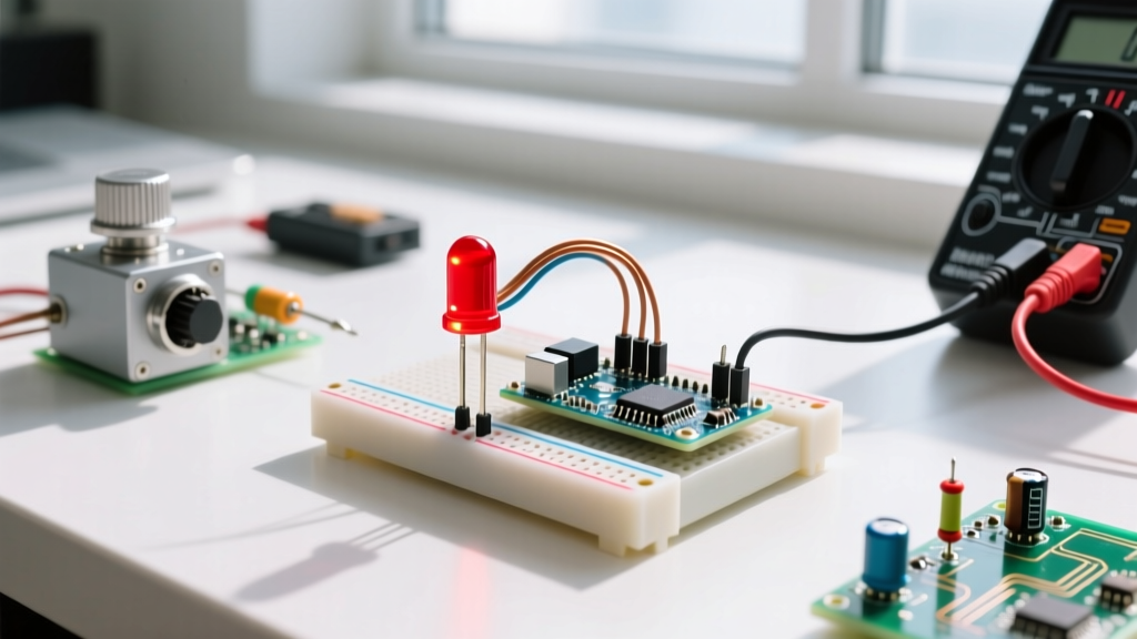
Binary to decimal conversion is the mathematical process of translating a base-2 number (using only 0s and 1s) into a base-10 number by multiplying each bit by its corresponding power of two and summing the results. In a real circuit or installation, this conversion changes how you interpret physical hardware states—like reading a bank of DIP switches on a motor driver or decoding a logic analyzer trace—into human-readable decimal values for configuration. Beginners frequently confuse pure binary conversion with Binary-Coded Decimal (BCD) or hexadecimal shorthand, but standard binary treats the entire string of bits as a single continuous integer rather than grouping them into separate decimal digits or nibbles.
The Core Math: Step-by-Step Conversion
To understand the weighting of each bit, think of an 8-bit binary number like a row of eight light switches on a wall, where each switch controls a lamp that is exactly twice as bright as the one before it. The rightmost switch (Least Significant Bit, or LSB) controls a 1-watt lamp, the next controls a 2-watt lamp, then 4-watt, 8-watt, and so on. The total brightness is the sum of the switched-on lamps.
Here is the standard weighting table for an 8-bit byte, which is the most common data size you will encounter when configuring microcontroller registers or reading shift registers:
| Bit Position | 7 (MSB) | 6 | 5 | 4 | 3 | 2 | 1 | 0 (LSB) |
|---|---|---|---|---|---|---|---|---|
| Power of 2 | 2^7 | 2^6 | 2^5 | 2^4 | 2^3 | 2^2 | 2^1 | 2^0 |
| Decimal Weight | 128 | 64 | 32 | 16 | 8 | 4 | 2 | 1 |
Worked Numeric Example
Let's convert the binary byte 10110101 into a decimal value. We align the bits with their corresponding weights from the table above and add the weights where the bit is a 1:
- Bit 7 (1): 1 × 128 = 128
- Bit 6 (0): 0 × 64 = 0
- Bit 5 (1): 1 × 32 = 32
- Bit 4 (1): 1 × 16 = 16
- Bit 3 (0): 0 × 8 = 0
- Bit 2 (1): 1 × 4 = 4
- Bit 1 (0): 0 × 2 = 0
- Bit 0 (1): 1 × 1 = 1
Summing the active weights: 128 + 32 + 16 + 4 + 1 = 181. The binary value 10110101 is exactly 181 in decimal.
0b prefix. For example, int myVal = 0b10110101; is automatically compiled as the decimal integer 181. However, you still need to understand the underlying math when debugging raw data dumps from a logic analyzer.
Where You Meet This in Practice
You might wonder why you need to do manual binary to decimal conversion when compilers and calculators exist. In physical electronics and hardware debugging, you are often staring at physical switches, LED indicators, or raw hex/binary captures where the translation must happen in your head or on a scrap of paper.
1. DMX512 Lighting Addresses via DIP Switches
If you are wiring theatrical or architectural lighting, DMX512 fixtures use a 9-pin or 10-pin block of physical DIP switches to set their starting address. The switches represent binary weights from 1 to 256. If a lighting console is patched to send data for fixture 181, you must mentally convert 181 to binary to know which physical switches to flip ON. Using our previous math, 181 requires switches 1, 3, 5, 6, and 8 to be in the ON position. Getting this wrong means your moving head light will either go dead or start twitching erratically because it's listening to the wrong channel block.
2. I2C Address Configuration on Breakout Boards
Many I2C peripheral chips, such as the PCA9685 PWM driver or the MCP23017 GPIO expander, have physical address pins (usually labeled A0, A1, A2) that you tie to VCC (1) or GND (0) to change their I2C bus address. The base address for a PCA9685 is 0x40 (decimal 64). If you solder the A0 and A2 jumpers closed (logic 1) and leave A1 open (logic 0), your binary offset is 101. Converting binary 101 to decimal gives you 5. You add this offset to the base address: 64 + 5 = 69 (or 0x45 in hex). If you fail to convert the binary jumper state correctly, your Wire.beginTransmission() calls will silently fail, and your I2C scanner will show nothing.
3. Microcontroller GPIO Port Registers
When writing bare-metal code or optimizing high-speed pin toggling on an ESP32 or AVR, you write directly to port registers. According to the ESP32 Technical Reference Manual, writing a 1 to a specific bit in the GPIO_OUT_W1TS_REG (Write 1 to Set) register pulls that specific physical pin HIGH. If you want to simultaneously trigger pins 2, 4, and 7, you must construct a binary mask: 10010100. Converting this to decimal yields 148. You would write REG_WRITE(GPIO_OUT_W1TS_REG, 148); in your C code. Understanding this conversion is what separates a hobbyist who relies on slow digitalWrite() loops from an engineer who can toggle pins in nanoseconds.
Common Pitfalls and Edge Cases
While the math itself is straightforward, the way hardware implements binary data introduces several traps that can cause hours of debugging.
Endianness and Shift Registers: When clocking data into a shift register like the Texas Instruments SN74HC595, you must know whether the chip expects the Most Significant Bit (MSB) or Least Significant Bit (LSB) first. The 74HC595 shifts data in MSB-first. If you want output pin Q0 to be HIGH and the rest LOW, the decimal value is 1. But if you send the binary byte 00000001 MSB-first, the '1' gets pushed all the way down the chain and ends up on Q7, not Q0. You actually need to send 10000000 (decimal 128) to light up Q0. Always check the datasheet's shift direction arrow.
Signed vs. Unsigned Integers (Two's Complement): Standard binary to decimal conversion assumes unsigned integers (all positive). If you are reading a signed 8-bit value from an I2C temperature sensor or an accelerometer, the MSB acts as a sign bit. In an 8-bit signed system, 11111111 is not 255; it is -1. This is calculated using Two's Complement. If your logic analyzer shows a binary stream of 10000000 from a signed sensor, the decimal value is -128, not +128. Misinterpreting signed binary as unsigned will cause your motor control loops or thermal shutdowns to fail catastrophically when the values cross zero.
Frequently Asked Questions
How to do binary to decimal conversion for fractional numbers?
Fractional binary conversion uses negative powers of two for the bits to the right of the binary point (the equivalent of a decimal point). The first bit after the point is 2^-1 (0.5), the second is 2^-2 (0.25), the third is 2^-3 (0.125), and so on. For example, the binary number 10.11 converts to decimal by adding the integer part (1×2 + 0×1 = 2) and the fractional part (1×0.5 + 1×0.25 = 0.75), resulting in a decimal value of 2.75. This is heavily used in floating-point arithmetic inside microcontroller math coprocessors, though you rarely calculate it by hand in DIY electronics.
What is the fastest way to convert binary to decimal in my head?
The fastest mental method is 'running addition' from left to right (MSB to LSB). Start with a mental total of zero. For every bit you read, double your current total, and if the bit is a '1', add one. Let's use 1011: Start with 0. First bit is 1: double 0 and add 1 (Total = 1). Next bit is 0: double 1 and add 0 (Total = 2). Next bit is 1: double 2 and add 1 (Total = 5). Final bit is 1: double 5 and add 1 (Total = 11). This avoids having to memorize the 128/64/32/16 weighting table and works for binary strings of any arbitrary length, which is incredibly useful when reading 12-bit or 16-bit ADC values off an oscilloscope screen.
How to do binary to decimal conversion when reading a shift register?
When reading parallel data into a serial stream via a shift-in register (like the 74HC165), the physical wiring dictates the binary order. If your physical switch bank is wired so that Switch 1 goes into the D0 pin and Switch 8 goes into the D7 pin, the binary string you receive in your microcontroller's SPI buffer will exactly match the physical layout. However, if the PCB designer routed the traces backward (Switch 1 to D7, Switch 8 to D0), your binary string will be reversed. If you read 10000000 but expected Switch 1 to be ON, you must reverse the bit order in software before doing your binary to decimal conversion. In Arduino C++, you can use a bitwise reversal function or simply map the physical pins correctly in your schematic review phase to avoid software patching.