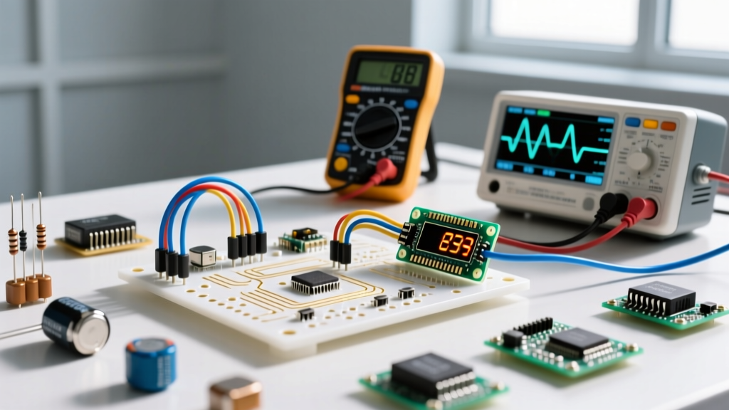

A band pass filter is a circuit that allows a specific range of frequencies to pass through while attenuating frequencies both below and above that range. When you insert this filter into a signal path, it fundamentally changes the noise floor of your circuit by stripping out low-frequency drift (like 60Hz mains hum or thermal DC offset) and high-frequency interference (like switching ripple or RF noise), leaving only your target signal intact. Hobbyists and students commonly confuse it with a band-stop (notch) filter, which blocks a specific band while passing everything else, or they mistakenly assume that simply wiring a passive high-pass and low-pass filter together will yield a perfect response without accounting for impedance loading effects.
The Core Mechanics and the "Speed Limit" Analogy
To understand how a band pass filter (BPF) shapes a signal, think of it like a specialized highway tunnel that enforces both a minimum and maximum speed limit. Cars (frequencies) moving too slowly are turned away at the entrance ramp, and cars moving too fast are blocked at the exit. Only vehicles traveling within the designated speed band make it through to the other side. In electronics, the "entrance ramp" is your high-pass stage, the "exit" is your low-pass stage, and the "tunnel" is the passband where your signal experiences minimal attenuation.
Every BPF is defined by three critical parameters:
- Center Frequency ($f_c$): The midpoint of the passband where the signal transfer is at its maximum.
- Bandwidth (BW): The difference between the upper ($f_H$) and lower ($f_L$) -3dB cutoff frequencies.
- Quality Factor (Q): The ratio of the center frequency to the bandwidth ($Q = f_c / BW$). A higher Q means a narrower, more selective filter.
Worked Numeric Example: Designing a 1kHz Active Filter
Let’s design a broad active band pass filter to isolate a 1kHz audio tone, passing frequencies from 800 Hz to 1200 Hz. We will use a cascaded active RC topology with an LM358 dual op-amp to provide buffering and prevent loading.
Step 1: Define the Cutoffs
- Lower cutoff ($f_L$) = 800 Hz
- Upper cutoff ($f_H$) = 1200 Hz
Step 2: Calculate the High-Pass Stage (Blocks < 800 Hz)
We will use a standard 100 nF (0.1 µF) ceramic capacitor for $C_1$. The formula for the cutoff frequency is $f = 1 / (2 \pi R C)$.
Rearranging for R: $R_1 = 1 / (2 \pi \times 800 \times 100 \times 10^{-9})$
$R_1 = 1,989 \Omega$. We will use a standard 2 kΩ resistor.
Step 3: Calculate the Low-Pass Stage (Blocks > 1200 Hz)
Using the same 100 nF capacitor for $C_2$ to keep our BOM simple:
$R_2 = 1 / (2 \pi \times 1200 \times 100 \times 10^{-9})$
$R_2 = 1,326 \Omega$. We will use a standard 1.3 kΩ resistor (or a 1.2 kΩ in series with a 100 Ω).
Step 4: Buffer and Verify
Wire the high-pass output into the non-inverting input of the first LM358 op-amp stage (configured as a voltage follower). Feed that output into the low-pass RC network, and buffer the final output with the second half of the LM358. If you sweep this with a function generator and oscilloscope, you will see a flat peak between 800 Hz and 1200 Hz, rolling off at -20 dB/decade on both sides.
Where You Meet This in Practice
You will rarely see a textbook BPF in a commercial product, but you will see its functional equivalents everywhere. Here is where band pass filtering is doing the heavy lifting in real installations and designs:
- Ultrasonic Sensors: Distance sensors like the HC-SR04 use 40kHz piezo transducers. The receiver circuit employs a tight BPF to ignore 20kHz motor whine and 100kHz buck-converter ripple, triggering only on the 40kHz echo.
- Biomedical Instrumentation: An ECG machine must isolate the heart's electrical activity (roughly 0.5 Hz to 40 Hz). A BPF removes the 0 Hz DC baseline wander from breathing and the 50/60 Hz mains interference from the room's wiring.
- Audio Crossovers: In a 3-way speaker system, the midrange driver is fed by a BPF that blocks deep bass (which would cause cone over-excursion) and high treble (which the midrange driver cannot physically reproduce).
- Radio Frequency (RF) Receivers: Superheterodyne receivers use intermediate frequency (IF) band pass filters—often ceramic or crystal filters—to select a single radio station while rejecting adjacent channels.
Real-World Scenario Walkthrough: The 40kHz Ultrasonic Failure
Theory is clean; the workbench is not. Here is a scenario that highlights a classic BPF design failure involving op-amp limitations.
The Setup: I was building a custom ultrasonic anemometer (wind speed sensor) using 40kHz piezo transducers. The environment was electrically noisy, filled with 20kHz PWM motor drivers and 150kHz switching ripple from a nearby DC-DC converter. I needed a tight active Multiple Feedback (MFB) band pass filter centered exactly at 40kHz with a Q of 10 to isolate the acoustic echo.
The Numbers: Using standard MFB design equations (detailed in Texas Instruments application note SLOA024), I calculated the resistors and capacitors for a center frequency of 40,000 Hz and a Q of 10. I grabbed an LM358 op-amp from my bench bin because it was cheap, readily available, and worked fine for my 1kHz audio tests.
The Outcome: When I injected a 40kHz sine wave from my function generator, the output was attenuated by nearly -20dB instead of showing the expected gain. The filter was acting like a aggressive low-pass filter, completely killing my target signal.
What Went Wrong: I ignored the op-amp's Gain-Bandwidth Product. The LM358 has a GBP of roughly 1 MHz. For a 40kHz filter with a Q of 10, the required GBP is $10 \times 10 \times 40,000 = 4$ MHz. The LM358 simply couldn't slew fast enough to maintain the feedback loop at 40kHz, causing the phase margin to collapse and the high-frequency passband to choke. I swapped the LM358 for an NE5532 (GBP of 10 MHz), and the filter immediately produced a clean, amplified 40kHz peak. Always check the datasheet's GBP before finalizing your BOM for high-frequency active filters.
Frequently Asked Questions
Can I just use passive components (R, L, C) for a band pass filter?
Yes, but passive LC filters require bulky, expensive inductors that can pick up stray magnetic fields. Passive RC filters suffer from severe signal attenuation (insertion loss) and loading effects. For frequencies below 100kHz, active filters using op-amps, resistors, and capacitors are almost always the superior choice.
What is the difference between a band pass filter and a band stop filter?
A band pass filter passes the frequencies inside the target window and blocks the outside. A band stop filter (also called a notch filter) blocks the frequencies inside the target window and passes the outside. You use a notch filter to kill a specific noise source (like a 60Hz hum) without altering the rest of the audio or data signal.
Why does my simulated filter look different from my breadboard prototype?
Simulations assume ideal components. On the breadboard, ceramic capacitors (especially X7R and Y5V dielectrics) lose capacitance as DC bias voltage increases, and breadboard parasitic capacitance (usually 2pF to 5pF per node) will shift high-frequency cutoffs. For tight tolerances, use C0G/NP0 dielectric capacitors and transition to a soldered PCB as soon as possible.


