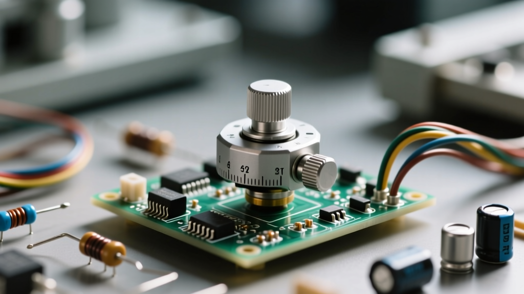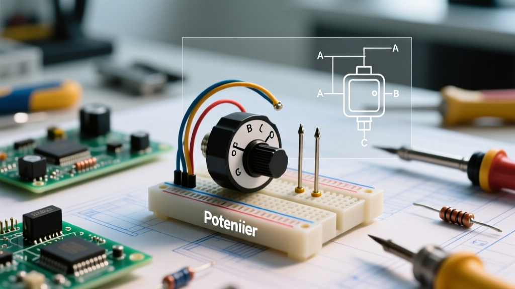

When sourcing components for custom electronics, you will often encounter surplus listings, vintage synth teardowns, or supplier catalogs where you only have a picture of a potentiometer to evaluate. Unlike resistors or capacitors, which are easily identified by standard color bands or ceramic housings, variable resistors come in a staggering array of mechanical form factors, tapers, and terminal configurations. Misinterpreting a low-resolution catalog image can lead to PCB layout disasters, mismatched knobs, or ruined audio dynamics.
In this project-based guide, we will dissect the visual cues hidden in component photos and apply them to a practical build: a 3-channel Lo-Fi audio mixer. By learning how to read a picture of a potentiometer critically, you can confidently order parts, design accurate KiCad footprints, and avoid costly prototyping errors.
The Visual Anatomy: Decoding the Photo
A high-quality component photo reveals three critical mechanical zones. When analyzing an image, zoom in on these specific areas to extract dimensional data before you even look at the datasheet.
1. Shaft Geometry and Length
The shaft dictates your knob compatibility. In a picture, look for the cross-section shape:
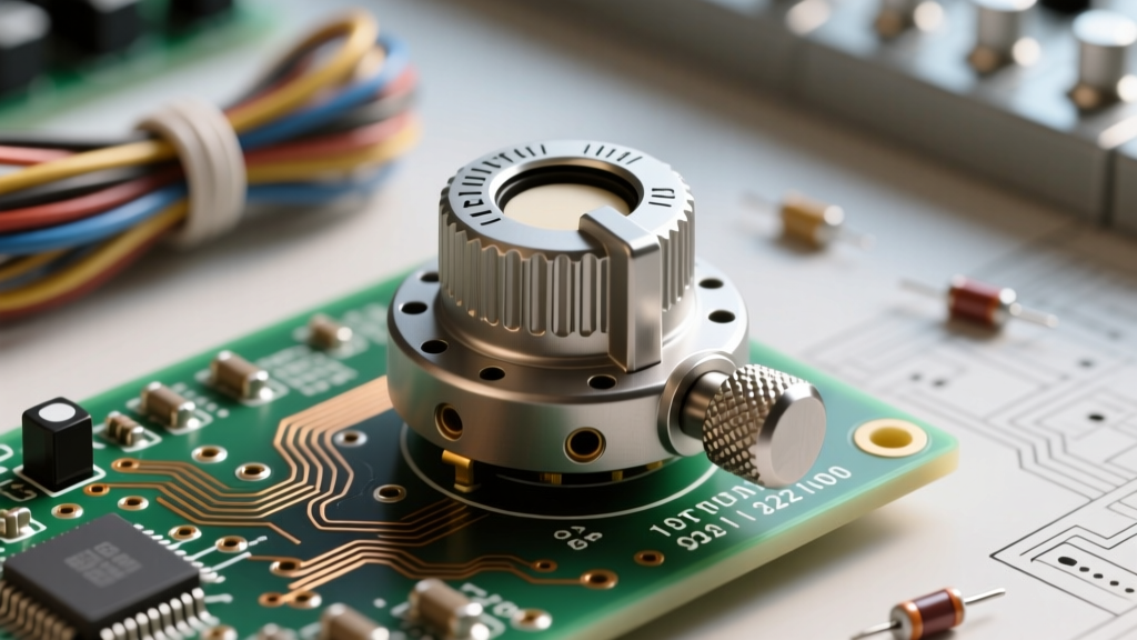
- Knurled (Split) Shafts: Usually 6mm in diameter with a split down the middle. Common in budget audio gear and guitar pedals. They rely on friction and a push-fit knob.
- D-Shafts: Typically 6mm with one flat side. These prevent knob slippage and are standard in modern modular synthesizers. Look for the flat edge reflection in the photo.
- Round with Set-Screw: Usually 6.35mm (1/4 inch). You will see a small divot or threading near the tip where a grub screw tightens. Standard on full-sized DJ mixers and studio gear.
Pro Tip: If the photo includes a standard 7mm threaded bushing, use the bushing's known diameter as a scale reference to estimate the shaft length (e.g., 15mm vs. 20mm) to ensure it will clear your enclosure's front panel.
2. Bushing and Mounting Hardware
The threaded bushing is the metal cylinder surrounding the shaft. Most standard 9mm and 16mm rotary pots feature a 7mm diameter, 7mm long threaded bushing (often M7 x 0.75 thread pitch). If the picture shows a smooth, unthreaded metal collar, you are likely looking at a snap-in or bracket-mount potentiometer, which requires a specific PCB mounting bracket rather than a panel-mount nut.
3. Terminal Configuration
Look closely at the base of the housing. Are the pins pointing straight down (PCB mount, typically 5mm or 0.2-inch pitch) or are they bent at a 90-degree angle for right-angle board mounting? Alternatively, you might see long, flat solder lugs with eyelets, indicating a panel-mount design meant for point-to-point hand wiring.
Project Scenario: Building a 3-Channel Lo-Fi Mixer
Let's apply this to a real-world project. We are designing a passive 3-channel audio mixer. Human hearing is logarithmic, meaning a linear increase in voltage does not sound like a linear increase in volume. Therefore, we absolutely need Audio Taper (Logarithmic) potentiometers for our volume faders. If we accidentally order Linear taper pots, the volume will appear to jump from 0% to 80% in the first quarter-turn of the knob.
Taper Identification From Visual Markings
When examining a picture of a potentiometer, the taper is usually stamped on the metal casing or printed on the bakelite housing. According to SparkFun's potentiometer guide, international coding standards vary by manufacturer:
- Asian Standard (Alpha, Bourns):
A= Audio (Log),B= Linear,C= Reverse Audio. A marking of B10K means 10,000 ohms, Linear. A10K means 10,000 ohms, Audio. - European Standard (Older Piher, Preh):
A= Linear,C= Log/Audio. (This is the exact opposite and a frequent source of catastrophic ordering errors).
If the picture is too blurry to read the stamp, check the supplier's part number. For example, the Bourns PTV09A series on Mouser clearly denotes taper in the SKU: PTV09A-4015F-A103 (A = Audio, 103 = 10k ohms).
Reference Table: Decoding Common Potentiometer Stamps
Use this quick-reference table when trying to decipher the faint laser etchings visible in supplier photos.
| Visual Stamp | Manufacturer Origin | Resistance Value | Taper Type | Mixer Application |
|---|---|---|---|---|
| A10K | Asian (Alpha/Bourns) | 10,000 Ω | Audio (Logarithmic) | Channel Volume Fader |
| B50K | Asian (Alpha/Bourns) | 50,000 Ω | Linear | Crossfader / Panning |
| 10KΩ LIN | US / European | 10,000 Ω | Linear | Control Voltage (CV) Offset |
| 10KΩ LOG | US / European | 10,000 Ω | Audio (Logarithmic) | Channel Volume Fader |
| C10K | Asian | 10,000 Ω | Reverse Audio | Specialty Fade-in Effects |
Translating the Image to KiCad Footprints
Once you have identified the physical dimensions from the picture, you must translate this into your PCB design software. If you are using the highly popular Bourns PTV09A 9mm rotary potentiometer, the datasheet confirms a standard 5mm pitch between the three main terminals, and a 10mm offset to the two mounting lugs.
The CAD Scaling Trick: If you only have a top-down picture and no datasheet, open the image in KiCad's footprint editor as a background layer. Draw a circle exactly 7.0mm in diameter (the universal standard for the threaded bushing). Scale the background image until the bushing in the photo perfectly matches your 7mm CAD circle. You can now accurately trace the pinout spacing, which is almost guaranteed to be a multiple of 1.27mm or 2.54mm for through-hole components.
Common Sourcing Pitfalls When Relying on Photos
Relying solely on a picture of a potentiometer without verifying the mechanical drawing leads to specific, frustrating failure modes in DIY projects:
- The Detent Illusion: Many photos crop out the top of the shaft. You might order what looks like a standard smooth shaft, only to receive a "center-detent" pot (which clicks into a physical notch at the 12 o'clock position). These are meant for stereo balance controls, not smooth volume sweeping.
- Switch-Backed Pots: Look closely at the rear of the housing in the photo. If there is an extra set of large solder lugs protruding from the back, it is a "push-pull" or "switch-backed" potentiometer. These require a deeper enclosure clearance (often an extra 8-10mm) to accommodate the internal switch mechanism.
- Wiper Pin Confusion: In a standard 3-pin layout, Pin 2 (the middle pin) is the wiper. However, some right-angle PCB mount pots stagger the pins. If the picture shows an asymmetrical pin layout, you must physically test the wiper with a multimeter upon arrival before soldering it into your mixer circuit.
Project Builder's Rule of Thumb: Never finalize your front-panel laser cutting or 3D printing until you have the physical potentiometer in hand. Catalog pictures frequently misrepresent shaft lengths and bushing widths by a millimeter or two, which is enough to cause your custom knobs to scrape against the enclosure faceplate.
Final Verification: The 50% Multimeter Test
When your parts arrive based on your photo analysis, verify the taper before soldering. Connect your multimeter probes to Pin 1 (Ground) and Pin 2 (Wiper). Turn the shaft exactly to the mechanical 50% mark. If it is a 10k Audio Taper pot, the meter should read roughly 1.5kΩ to 2kΩ (due to the logarithmic curve). If it reads exactly 5kΩ, you were sent a Linear taper pot by mistake, and it must be relegated to a CV control or panning circuit rather than your main audio mixer faders.