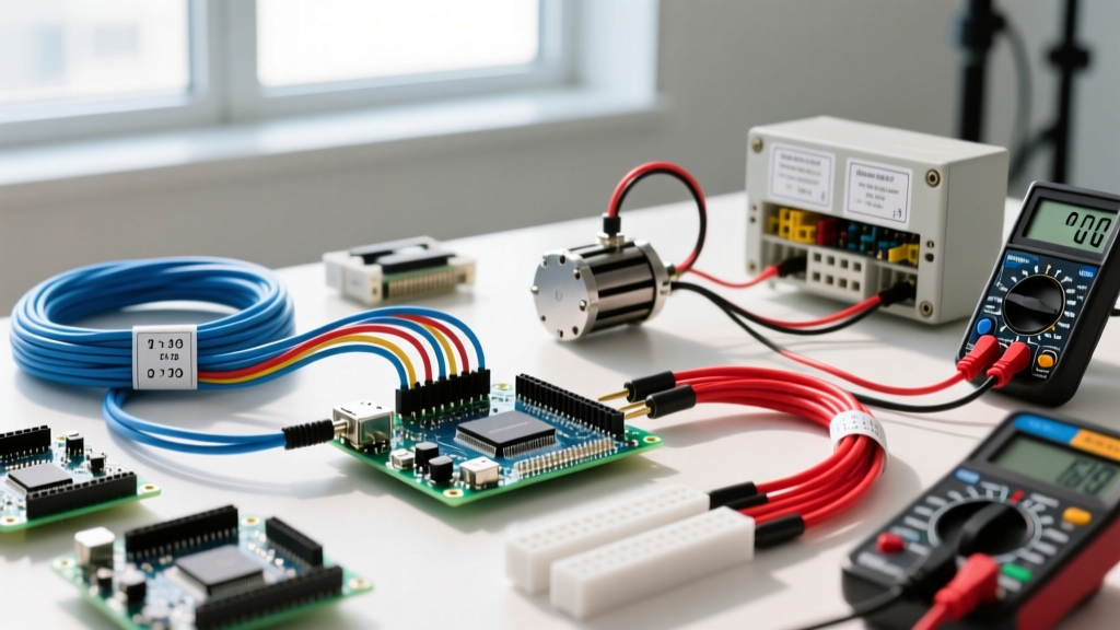
Accurate amps measurement is the definitive test of whether a circuit is actually doing the work you designed it to do. Voltage tells you the potential, and resistance tells you the restriction, but current (amps) reveals the real-time physical effort of the electrons moving through the wire. Depending on your application, you will either force the current through an internal shunt resistor (inline multimeter) or measure the magnetic field generated by the current flow (clamp meter).
The direct answer to "how do I measure amps" depends on the circuit: use a clamp meter for AC loads over 1A without breaking the circuit, and use an inline digital multimeter (DMM) for DC circuits, low-current electronics, or when you need precision down to the microamp. Below is the complete bench and jobsite framework for getting reliable numbers without blowing your meter's internal fuse or misdiagnosing a fault.
Meter Setup, Lead Jacks, and Safety Categories (CAT)
Before you touch a probe to a terminal, your meter must be configured correctly. The most common way hobbyists and apprentices destroy their multimeters is by leaving the red lead in the 10A jack and then attempting to measure voltage, or by routing a 2A load through the delicate milliamp shunt.
Standard DMM Setup Block for Inline Amps Measurement
- Dial Position: Set to A⎓ (DC Amps) or A~ (AC Amps). Never leave it on Auto if your meter separates voltage and current auto-ranging.
- Lead Jacks: Black lead always goes to COM. Red lead goes to the 10A (or 20A) jack for loads expected to exceed 200mA. Red lead goes to the mA/µA jack only for low-power logic circuits (under 200mA).
- Range Selection: If using a manual-ranging meter, always start at the highest range (10A) and step down. Starting on the 400mA range with an unexpected 2A inrush will instantly blow the internal glass fuse.
Expected Amps Readings: Good vs. Bad Values
A raw number on a screen is useless without context. A reading of 8.5A might be perfectly normal for a space heater on a low setting, but catastrophic for a 5A motor. The table below provides baseline expected values for common DIY and trade scenarios, including the numerical thresholds that indicate a healthy circuit versus a failing component.
| Device / Load | Nominal Voltage | Expected Amps (Run) | Good Range (Acceptable) | Bad Reading & Probable Cause |
|---|---|---|---|---|
| 1500W Space Heater | 120V AC | 12.5A | 11.8A – 13.0A | <10A: Failing element / >15A: Short or voltage sag |
| 12V Compressor Fridge | 12V DC | 4.5A | 4.0A – 6.0A (Startup spike to 12A is normal) | >10A continuous: Seized rotor or low voltage brownout |
| WS2812B LED Strip (60 LEDs) | 5V DC | 3.6A (Full White) | 3.2A – 3.8A | <2.0A: Severe voltage drop in undersized feed wires |
| ESP32 DevKit (Active WiFi TX) | 3.3V DC | 160mA | 120mA – 240mA | >400mA: GPIO shorted to ground or failed voltage reg |
| Standard 1/2 HP Sump Pump | 120V AC | 6.0A | 5.5A – 7.5A (LRA up to 30A) | >10A running: Impeller jam or failing start capacitor |
When evaluating these numbers, remember that AC loads are highly sensitive to line voltage. A space heater pulling 12.5A at 120V will only pull 11.4A if your utility is delivering 110V at the end of a long feeder run. Always measure voltage concurrently if your amp reading seems slightly off-nominal.
Probe Placement and Measurement Techniques
How you physically interface the meter with the circuit dictates the accuracy of your amps measurement. The physics of inline versus clamped measurements require entirely different probe placements.
Inline Multimeter (Series Connection)
To measure current with a standard DMM, the meter must become part of the circuit. Current is the flow of electrons; if you don't force the electrons to pass through the meter's internal shunt resistor, you cannot count them.
- De-energize the circuit. Never break a live DC circuit under load if it contains heavy inductance (like a large motor), as the collapsing magnetic field will arc across your probe tips.
- Break the positive leg. Disconnect the positive (hot) wire from the power source or load. Leave the negative (ground/neutral) intact.
- Place the probes. Touch the red probe to the positive wire coming from the power source. Touch the black probe to the positive terminal on the load. Current flows from the source, through the red probe, through the meter's shunt, out the black probe, and into the load.
- Energize and read. Power the circuit. If the reading shows a negative sign (e.g., -4.2A), your probes are simply reversed relative to the DC flow; the magnitude is still correct.
Clamp Meter (Non-Contact AC/DC)
Clamp meters use either a Current Transformer (AC only) or a Hall Effect sensor (AC/DC) to read the magnetic field surrounding a conductor.
- The Golden Rule: You must clamp only one conductor at a time.
- The NM-B Cable Mistake: If you clamp your jaws around an entire Romex cable (containing both the hot and neutral wires), the magnetic fields generated by the current flowing out on the hot wire and returning on the neutral wire are exactly equal and opposite. They cancel each other out, and the meter will read 0.00A, even if the circuit is pulling 15A.
- The Fix: You must separate the conductors. Use a line splitter (like the Gardner Bender GCL-101) plugged between the wall and the appliance, or clamp the individual THHN wire inside a panel (requires CAT-rated PPE and extreme caution).
Common Mistakes That Yield Misleading Amps Measurements
Even with the right tool, subtle electrical phenomena can trick you into misdiagnosing a circuit. Here are the specific failure modes that corrupt amps measurements.
1. Burden Voltage in Low-Voltage DC Circuits
Every inline multimeter has an internal shunt resistor used to measure current. When current flows through this resistor, it drops a small amount of voltage—known as burden voltage. On the 10A range, this shunt might be 0.01Ω, dropping 0.01V per amp. But on the mA range, the shunt might be 1Ω to 10Ω.
The Trap: If you are measuring the current of a 3.3V ESP32 microcontroller on the mA range, and the meter's internal shunt is 2Ω, a 150mA current draw will drop 0.3V across the meter. Your ESP32 now only sees 3.0V. This can trigger a brownout reset, causing the current to drop to zero, making you think the board is dead when it's actually your meter starving it of voltage. Fix: Use a dedicated bench power supply with a built-in shunt display, or measure the voltage at the load simultaneously to account for the drop.
2. Inductive Coupling and Ghost Readings on Clamps
High-sensitivity Hall effect clamp meters can pick up stray magnetic fields from adjacent conductors in a crowded breaker panel. If you are measuring a 120V lighting circuit pulling 0.5A, but the clamp is resting against a 50A electric range feeder, the magnetic bleed-over can artificially inflate your reading by 10-20%. Always zero-out (rel-zero) your clamp meter away from all conductors before taking a low-current reading.
3. Inrush Current vs. Steady-State
Motors, compressors, and large capacitor banks draw massive Locked Rotor Amps (LRA) or inrush current for the first 50 to 200 milliseconds of startup. A standard DMM sampling at 2Hz will completely miss this spike. If you need to measure inrush to size a breaker or verify a soft-start circuit, you must use a clamp meter with a dedicated "INRUSH" button (like the Fluke 376 FC), which triggers a high-speed 100ms sampling window to capture the true peak startup current. Standard multimeter current measurement techniques will only show you the steady-state running amps.
By respecting the physical limitations of your test equipment, matching the tool to the specific current range, and understanding the magnetic environment of your test point, your amps measurements will transition from rough guesses to precise, actionable diagnostic data.