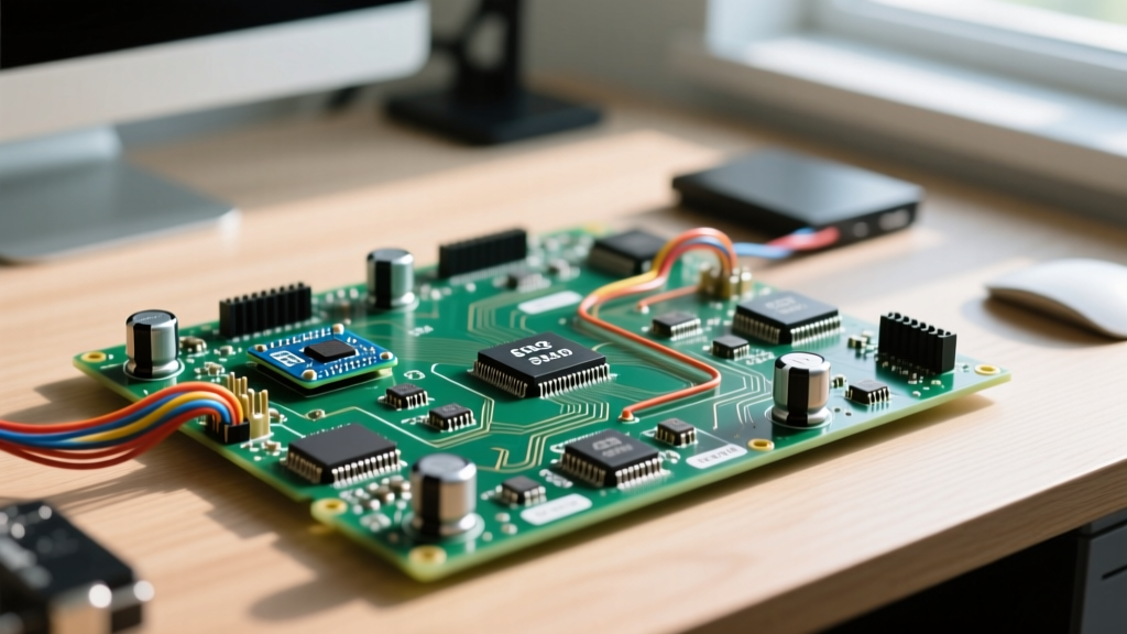
An amplitude modulator is a nonlinear circuit that varies the peak voltage (amplitude) of a high-frequency carrier wave in direct proportion to the instantaneous voltage of a lower-frequency message signal. In a real RF installation, this process shifts the baseband audio or data spectrum up to the carrier frequency, creating upper and lower sidebands that allow the signal to be radiated efficiently by an antenna of practical size and enabling frequency-division multiplexing. Beginners commonly confuse amplitude modulators with simple audio amplifiers (which merely increase signal magnitude without shifting the frequency spectrum) or ring modulators (which suppress the carrier entirely to produce double-sideband suppressed-carrier signals).
The Core Math: Modulation Index and Sideband Generation
To understand what an amplitude modulator actually does to a signal, we have to look at the math of the modulation index ($m$) and the resulting frequency spectrum. The modulation index defines the depth of the amplitude variation and is calculated as the ratio of the message signal's peak voltage ($V_m$) to the carrier signal's peak voltage ($V_c$).
Worked Numeric Example
Let's calculate the exact output of an amplitude modulator driven by a 1.000 MHz RF carrier and a 5 kHz audio tone.
- Carrier ($V_c$): 10V peak at 1.000 MHz
- Message ($V_m$): 8V peak at 5 kHz (5,000 Hz)
- Modulation Index ($m$): $8V / 10V = 0.8$ (80% modulation)
The amplitude modulator mathematically multiplies these signals, which generates sum and difference frequencies. The output spectrum will contain exactly three discrete frequencies:
- Carrier: 1.000 MHz (unchanged in frequency, but its amplitude now fluctuates)
- Upper Sideband (USB): $1.000 \text{ MHz} + 5 \text{ kHz} = 1.005 \text{ MHz}$
- Lower Sideband (LSB): $1.000 \text{ MHz} - 5 \text{ kHz} = 0.995 \text{ MHz}$
Power distribution in an AM signal is highly inefficient because the carrier itself contains no audio information. If our unmodulated carrier delivers 100 Watts into a 50-ohm dummy load, we can calculate the total transmitted power ($P_t$) using the standard AM power formula: $P_t = P_c \times (1 + m^2 / 2)$.
| Signal Component | Frequency | Power Calculation | Power (Watts) |
|---|---|---|---|
| Carrier | 1.000 MHz | $P_c$ | 100 W |
| Upper Sideband | 1.005 MHz | $P_c \times (m^2 / 4)$ | 16 W |
| Lower Sideband | 0.995 MHz | $P_c \times (m^2 / 4)$ | 16 W |
| Total Transmitted | N/A | $100 \times (1 + 0.8^2 / 2)$ | 132 W |
Inside the Circuit: How Analog Multipliers Generate AM
You cannot generate standard AM by simply feeding audio and RF into a linear summing amplifier. Linear addition just creates a composite waveform; it does not create the sidebands required for modulation. You need a nonlinear device or an analog multiplier to force the two signals to interact mathematically.
The classic equation for an analog multiplier is $V_{out} = K \cdot V_1(t) \cdot V_2(t)$. However, if you multiply a pure AC carrier by a pure AC audio signal, the carrier is suppressed (this is how a ring modulator works). To generate standard AM with a carrier, we must add a DC offset to the message signal before it enters the multiplier:
$V_{out}(t) = [V_{DC} + V_m(t)] \cdot V_c(t)$
Common Amplitude Modulator ICs
- Motorola MC1496 / NXP NE612: These are based on the Gilbert Cell topology. They use a cross-coupled differential transistor pair to perform the multiplication. They are inexpensive, operate up to VHF frequencies, and are the standard choice for hobbyist ham radio transceivers and undergraduate RF labs.
- Analog Devices AD633: A modern, precision four-quadrant analog multiplier. While more expensive (typically $15-$25 per chip), it requires almost no external trimming and provides a highly linear transfer function, making it ideal for instrumentation and software-defined radio (SDR) analog front-ends.
Where You Meet Amplitude Modulators in Practice
While digital modulation schemes (QAM, OFDM) dominate modern Wi-Fi and cellular networks, analog amplitude modulators remain critical in specific, high-reliability applications.
Aviation VHF Communications (118 - 137 MHz)
Commercial and general aviation radios strictly use amplitude modulators rather than Frequency Modulation (FM). According to FCC aviation radio regulations and international ICAO standards, AM is mandated to prevent the "FM capture effect." In an FM receiver, if two stations transmit on the same frequency, the receiver will lock onto the stronger signal and completely mute the weaker one. In aviation, if a pilot with a weak transmitter tries to issue a distress call over a stronger, routine transmission, ATC must be able to hear the weaker signal heterodyning in the background. AM allows both signals to pass through the receiver simultaneously.
Standard AM Broadcast (530 - 1700 kHz)
The medium-wave broadcast band relies on high-level plate modulation in massive tube amplifiers, or solid-state PWM (Pulse Width Modulation) amplitude modulators in modern 50kW+ transmitter sites. The long wavelengths require massive antennas, but the simple envelope detector in a $5 pocket radio makes the receiver side incredibly cheap to manufacture.
RFID and Near-Field Communication
Passive 125 kHz and 13.56 MHz RFID tags use load modulation, a form of amplitude modulation. The reader generates a strong carrier field. The passive tag modulates the amplitude of that field by switching a load resistor across its internal coil, which slightly alters the Q-factor of the reader's antenna circuit. The reader's amplitude modulator/demodulator circuit detects these tiny voltage dips to read the tag's data.
Measuring and Troubleshooting AM Signals
When debugging an amplitude modulator circuit on the bench, a standard multimeter is useless. You need an oscilloscope to verify the modulation envelope and ensure you are not overmodulating.
- Time-Domain Envelope View: Connect the scope probe to the modulator output. Set the timebase to display several cycles of the audio message frequency (e.g., 500 µs/div for a 1 kHz tone). You should see the high-frequency RF carrier filling a shape that perfectly mirrors the audio sine wave. If the peaks of the envelope flatten out, your $V_m$ is too high, and you are overmodulating ($m > 1.0$).
- X-Y Trapezoid Pattern: This is the gold standard for precise measurement. Feed the modulator's audio input into the scope's Channel 1 (X-axis). Feed the modulator's RF output (passed through a simple diode envelope detector) into Channel 2 (Y-axis). Switch the scope to X-Y mode.
Frequently Asked Questions
Why do aviation radios use amplitude modulators instead of FM?
Aviation radios use amplitude modulators to avoid the FM capture effect. In FM, a stronger signal on the same frequency will completely silence a weaker signal. Amplitude modulation allows multiple signals on the same frequency to be heard simultaneously as a heterodyne beat, ensuring that a weaker emergency distress call can still be heard by air traffic control even if another aircraft is transmitting at a higher power level.
What is the difference between an amplitude modulator and a ring modulator?
Both circuits multiply two signals together, but a standard amplitude modulator adds a DC offset to the message signal before multiplication, preserving the carrier frequency in the output spectrum. A ring modulator (often built with a diode ring or a Gilbert cell without DC bias) multiplies two pure AC signals. This suppresses the carrier entirely, outputting only the upper and lower sidebands (Double-Sideband Suppressed-Carrier, or DSB-SC). Ring modulators are used in SSB (Single Sideband) ham radio transmitters and analog synthesizers for frequency-shifting effects.
How do you measure the modulation index of an amplitude modulator output on an oscilloscope?
To measure the modulation index ($m$) using an oscilloscope in standard time-domain mode, capture the AM envelope and measure the maximum peak-to-peak voltage ($V_{max}$) and the minimum peak-to-peak voltage ($V_{min}$) of the envelope. Apply the formula: $m = (V_{max} - V_{min}) / (V_{max} + V_{min})$. For example, if the envelope peaks at 18V and dips to 2V, the calculation is $(18 - 2) / (18 + 2) = 16 / 20 = 0.8$, indicating 80% modulation.