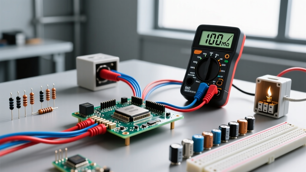
4-wire voltage measurement, also known as Kelvin sensing, is a technique that uses two separate pairs of wires—one to force current and one to measure voltage—to completely eliminate the resistance of the test leads from the final reading. In a real circuit or installation, it changes a highly inaccurate low-resistance or high-current measurement into a precise reading by ignoring the voltage drop across the probes themselves. People commonly confuse it with standard 2-wire measurement or industrial 4-20mA current loops, assuming more wires just means "better signal" rather than a specific physical separation of current and voltage paths.
The Physics of Lead Resistance (And Why 2-Wire Fails)
To understand why we need four wires, you first have to look at the catastrophic math behind standard 2-wire measurements on low-resistance components. Every piece of copper wire has resistance. A standard 3-foot pair of 18 AWG test leads might have a combined resistance of about 100 milliohms (0.100 Ω). When you measure a 10 kΩ resistor, 0.100 Ω of lead resistance is a 0.001% error—completely negligible.
But when you measure high-current shunts, battery internal resistance, or PCB traces, that lead resistance destroys your data.
Worked Numeric Example: The 50A Shunt Disaster
Imagine you are testing a 1 mΩ (0.001 Ω) current shunt designed to carry 50A. According to Ohm’s Law, the true voltage drop across this shunt at 50A should be:
V = I × R = 50A × 0.001Ω = 0.050V (50 mV)
If you use a standard 2-wire multimeter, the meter pushes its test current through the shunt and the test leads. Let’s assume your test leads have 50 mΩ (0.050 Ω) of resistance each. The meter actually measures the series combination of the shunt and the leads:
- Shunt Resistance: 0.001 Ω
- Lead 1 Resistance: 0.050 Ω
- Lead 2 Resistance: 0.050 Ω
- Total Loop Resistance: 0.101 Ω
At 50A, the meter reads: 50A × 0.101Ω = 5.05V.
Your true value was 0.050V. Your measured value is 5.05V. The error is 10,000%. This is why 2-wire measurements on sub-ohm components are practically useless.
How 4-Wire Voltage Measurement Solves the Problem
Four-wire measurement (often referred to in bench shorthand as a 4 voltage drop test) solves this by splitting the job into two distinct circuits: the Force pair and the Sense pair.
- The Force Pair: These two heavy-gauge wires carry the actual load current (or the meter's test current) through the DUT. They will experience a massive voltage drop, but we do not measure voltage across them.
- The Sense Pair: These two wires connect to a high-impedance voltmeter (typically >10 MΩ input impedance). Because the impedance is so high, virtually zero current flows through the sense wires.
Think of it like tapping a high-pressure water main with a microscopic pressure gauge that draws no actual water flow; because no water is flowing through the gauge's tap, there is no friction loss in the tap itself, and it reads the exact pressure of the main.
Since current (I) in the sense leads is essentially zero, the voltage drop (V = I × R) across the sense leads is also zero. The voltmeter reads only the voltage drop across the 1 mΩ shunt itself, completely ignoring the 100 mΩ of lead resistance in the force lines. As detailed in All About Circuits' guide to Kelvin measurement, this physical separation is what allows bench DMMs to resolve micro-ohm differences accurately.
Where You Meet This in Practice
You will encounter 4-wire voltage and Kelvin sensing requirements across several specific electrical and electronic domains:
- Battery Management Systems (BMS): When balancing LiFePO4 or Li-ion cells, the BMS must measure cell voltages to the millivolt. If the balance wires carry high current, 4-terminal sensing at the cell busbar ensures the BMS doesn't overcharge a cell due to wire voltage drop.
- RTD Temperature Sensors (PT100/PT1000): Resistance Temperature Detectors change resistance by fractions of an ohm per degree. A 3-wire or 4-wire connection is mandatory in industrial PLCs to prevent the sensor cable length from skewing the temperature reading.
- PCB Current Shunts: When designing a board with an INA219 or INA226 current monitor IC, the datasheet will explicitly mandate a Kelvin connection layout, routing the sense traces directly to the inner pads of the shunt resistor.
- Electroplating and Anodizing: High-current DC rectifiers use 4-wire sense lines to regulate voltage exactly at the chemical bath electrodes, compensating for the massive voltage drop across the heavy copper busbars.
Common Mistakes and Failure Modes
Even with the right equipment, technicians frequently ruin 4 voltage measurements with physical wiring errors.
The most common fatal error is connecting the sense leads "outside" the force leads. The force leads must connect to the outer edges of the DUT, and the sense leads must connect to the inner edges, directly at the resistive material. If you swap them, you are measuring the contact resistance of the alligator clips, which can easily add 50 mΩ of error back into your reading.
Using Standard Banana Plugs: Standard multimeter probes internally tie the force and sense paths together at the plug. To truly measure a 4-wire connection, you must use dedicated Kelvin clips (often called alligator-to-banana Kelvin probes), which maintain physical separation between the force jaw and the sense jaw all the way to the tip.
Ground Loops in Active Circuits: If you are using an oscilloscope or a bench power supply with a grounded chassis to perform a 4-wire measurement on a floating circuit, the ground reference of the sense leads can create a short circuit. Always verify if your measurement device's low-side sense terminal is tied to earth ground.
Frequently Asked Questions
Can I use a standard 2-wire multimeter for 4 voltage measurement?
No. A standard multimeter only has two input jacks (V/Ω and COM) and internally measures the voltage drop across its own internal shunt and the test leads combined. To perform a true 4-wire measurement, you need a bench DMM with dedicated 4-wire terminals (usually labeled Sense HI/LO and Input HI/LO) or a specialized milliohm meter.
What is the difference between 4-wire voltage and a 4-20mA current loop?
They are entirely different concepts that happen to use four wires. A 4-20mA loop is an industrial signaling protocol where a sensor modulates current to transmit data over long distances without signal degradation. A 4-wire voltage (Kelvin) measurement is a physical testing technique used to eliminate lead resistance when measuring low-ohm components.
Do the sense wires need to be the same AWG as the force wires?
No, and they shouldn't be. The force wires need to be thick enough to handle the load current without overheating or introducing excessive voltage drop that might exceed the compliance voltage of your power supply. The sense wires carry virtually zero current (microamps), so they can be very thin (e.g., 24 AWG or 28 AWG). Using thin sense wires makes them easier to route and solder directly to PCB pads.
Why does my 4-wire measurement fluctuate when I move the cables?
If your reading jumps when you wiggle the wires, you likely have a thermal EMF (electromotive force) issue or a loose mechanical connection. When dissimilar metals (like copper test leads and a brass terminal) are at slightly different temperatures, they generate micro-voltages (the Seebeck effect). In a 4-wire setup measuring micro-ohms, these thermal voltages appear as noise. Keep your sense connections clean, tight, and at a stable ambient temperature.