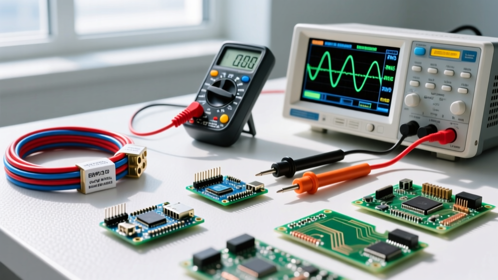
Choosing the right meter and setting it up correctly is the difference between a confident troubleshooting session and a blown internal fuse—or worse, an arc flash. While the basic physics of measuring voltage, current, and resistance remain constant, the hardware you use dictates your accuracy, especially on non-linear loads. Below is a practical, bench-and-jobsite guide to the 4 types of multimeter, complete with exact dial setups, probe placements, and the numeric thresholds that define a healthy circuit.
The 4 Types of Multimeter: Capabilities and Use Cases
Before touching a probe to a terminal, you need to know what your meter is actually calculating under the hood. The 4 types of multimeter found in modern electrical work each solve a specific measurement problem.
| Meter Type | Core Technology | Best Use Case | Accuracy on Non-Linear Loads | Typical Price Range | Reference Model |
|---|---|---|---|---|---|
| Analog | Moving coil (D'Arsonval) | Observing rapid voltage fluctuations and trending needles. | Poor (calibrated for pure sine waves only) | $300 - $550 | Simpson 260-6 |
| Standard DMM | Average-responding ADC | Basic DC circuits, resistive AC loads, and continuity. | Poor (reads ~20-40% low on VFDs or LED drivers) | $50 - $150 | Brymen BM235 |
| True RMS DMM | Thermal or computational RMS | Modern HVAC, VFDs, switched-mode power supplies, and lighting. | Excellent (calculates actual heating value of distorted waves) | $200 - $500 | Fluke 87V |
| Clamp Meter | Hall-effect or current transformer | Measuring high AC/DC current without breaking the circuit. | Varies (requires True RMS spec for distorted AC currents) | $150 - $400 | Fluke 376 FC |
If you are measuring the output of a variable frequency drive (VFD) or the input current of a server power supply, a Standard DMM will give you a dangerously misleading low reading. According to Fluke's engineering documentation on True RMS, average-responding meters assume a perfect sine wave and multiply the average by 1.111. On a distorted waveform, this math collapses, making True RMS mandatory for modern electronics and industrial controls.
Meter Setup Blocks and Probe Placement
Misplaced leads and wrong dial positions are the leading causes of blown meter fuses and misdiagnosed boards. Use these setup blocks for the three most common tests.
Test 1: 120V AC Receptacle (Mains Branch Circuit)
- Dial Position: V AC (often denoted as V~).
- Lead Jacks: Black lead into COM; Red lead into V/Ω.
- Range: Auto-range (or manually select 200V/600V if manual).
- Probe Placement: Insert the black probe into the wider slot (Neutral). Insert the red probe into the narrower slot (Hot). For ground verification, move the black probe to the U-shaped ground hole; the reading should remain identical.
Test 2: 12V DC Automotive or Solar Battery
- Dial Position: V DC (denoted as V⎓).
- Lead Jacks: Black lead into COM; Red lead into V/Ω.
- Range: 20V DC (manual) or Auto.
- Probe Placement: Press the black probe tip firmly against the negative (-) terminal. Press the red probe tip against the positive (+) terminal. If the reading shows a negative sign (e.g., -12.4V), your probes are reversed; swap them to verify polarity.
Test 3: AC Current Draw on a Compressor (Clamp Meter)
- Dial Position: A AC.
- Lead Jacks: Probes are not used for this test; rely on the clamp jaw.
- Range: Auto-range (ensure the meter is rated for the expected inrush, or use the Min/Max button to capture startup spikes).
- Probe Placement: Open the jaw and clamp around only one conductor (e.g., the black Line wire). Clamping around an entire Romex cable will yield a reading of 0.00A because the magnetic fields of the hot and neutral cancel each other out.
Expected Reading Tables: Good vs. Bad Values
A multimeter only gives you a number; your knowledge of the circuit dictates whether that number is acceptable. Below are the exact numeric thresholds for common diagnostic points.
| Test Point | Expected Good Reading | Bad Reading (Fault Indicated) | Common Mistake Giving Misleading Readings |
|---|---|---|---|
| 120V AC Receptacle (Line-to-Neutral) | 114.0V – 126.0V | < 110V (Voltage drop/loose neutral) or > 130V (Utility fault) | Using a Standard DMM on a modified sine-wave inverter backup; reads artificially low. |
| 240V Dryer/HVAC Outlet (Line-to-Line) | 228.0V – 252.0V | ~120V (Lost a phase/leg) or > 260V | Measuring Line-to-Neutral instead of Line-to-Line by accidentally probing the ground slot. |
| 12V Lead-Acid Battery (Resting, no load) | 12.60V – 12.80V | < 12.0V (Sulfated or deeply discharged cell) | Measuring immediately after removing a charger (surface charge reads >13.2V). Wait 30 mins. |
| 5V DC USB Power Rail (Under 1A load) | 4.75V – 5.25V | < 4.50V (Brownout condition, ESP32 will reset) | Probing with long, thin breadboard jumper wires, introducing a 0.3V drop before the meter. |
| Glass Fuse Continuity (Out of circuit) | < 0.5 Ω (and audible beep) | OL (Open Loop / Infinite resistance) | Measuring continuity while the fuse is still seated in a powered circuit (reads parallel paths). |
Safety Categories, CAT Ratings, and Misleading Readings
Measuring voltage is inherently dangerous when dealing with mains power. The most critical mistake a DIYer or junior tech can make is ignoring the CAT (Measurement Category) rating printed on the meter and the test leads. According to safety guidelines published by Fluke and IEC 61010 standards, the CAT rating defines the meter's ability to survive a transient voltage spike (arc flash) at a specific location in the electrical grid.
Before probing any circuit above 50V AC or 120V DC, de-energize the panel if you are terminating wires. If you must test live, wear appropriate PPE (arc-rated gloves and face shield for industrial panels). Ensure your meter and leads are rated for the environment. Never bypass a blown internal meter fuse with a standard glass fuse; it will turn your meter into a bomb during the next high-energy fault.
Which CAT Rating Do You Need?
- CAT II: Single-phase receptacle connected loads (appliances, portable tools, PC power supplies). Minimum for indoor home DIY.
- CAT III: Three-phase distribution, including single-phase commercial lighting, panel boards, and breaker boxes. Required for testing inside your main home electrical panel.
- CAT IV: Three-phase at utility connection, service entrance, outdoor overhead lines, and the primary side of the main transformer. Only required for utility workers and industrial service entrance diagnostics.
Why Your Readings Might Be Misleading
Beyond using the wrong meter type (Standard vs. True RMS), misleading readings usually stem from three physical errors:
- Ghost Voltages: When testing an open circuit running parallel to a live wire in the same conduit, capacitive coupling can induce a 'ghost' voltage of 30V to 80V on a high-impedance True RMS DMM. Use a meter with a low-Z (low impedance) mode to bleed off this phantom voltage and confirm the wire is actually dead.
- Current Measurement in Parallel: Moving the red lead to the 'Amps' jack and then probing across a live voltage source (in parallel) creates a dead short through the meter's shunt. This will instantly blow the internal HRC (High Rupturing Capacity) fuse, and potentially destroy the meter if it lacks proper protection. Always measure current in series with the load.
- Dirty Probe Tips: Oxidation on the metal probe tips can add 5 to 10 ohms of series resistance. When measuring low-resistance shunts or checking continuity on a ground bond, this yields a false 'bad' reading. Scrape the tips on a piece of sandpaper or steel wool before testing low-ohm circuits.
For further reading on electrical safety and hazard mitigation during live testing, refer to the OSHA Electrical Safety guidelines, which outline the strict boundary requirements for approaching exposed energized parts. Mastering the 4 types of multimeter isn't just about knowing which dial to turn; it's about understanding the physics of the circuit, the limitations of your hardware, and the absolute numeric thresholds that separate a healthy system from a failing one.