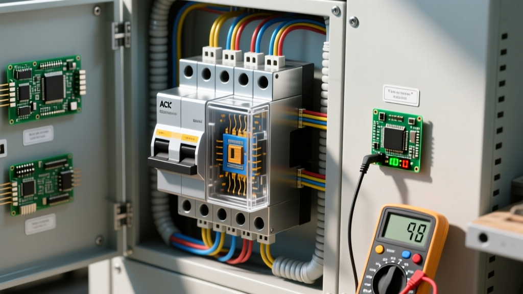
A 3ph transformer is a single magnetic core assembly with three sets of primary and secondary windings designed to step up or step down three-phase alternating current voltages simultaneously while maintaining the 120-degree phase separation. Unlike single-phase units that handle one AC sine wave, this device processes three overlapping waveforms, making it the backbone of commercial and industrial power distribution.
The Core Mechanics: What It Changes in a Real Circuit
In any electrical installation, a transformer fundamentally alters the voltage-to-current ratio. Think of it like a mechanical gear train: you can trade high torque (current) for high speed (voltage), but the total power (minus efficiency losses) remains constant. When you step down the voltage on a 3ph transformer, the secondary current increases proportionally, allowing you to transmit massive amounts of power over long distances at high voltage, then step it down to usable, safer levels at the point of use.
Beyond simple voltage conversion, a 3ph transformer changes two critical parameters in a real circuit:
- Galvanic Isolation: It physically separates the primary utility grid from the secondary building wiring, creating a "separately derived system" (per NEC Article 250) that requires its own local grounding electrode and bonding jumper.
- Phase Angle Shift: Depending on the winding configuration, the transformer can shift the phase relationship between primary and secondary. A Delta-Wye (Δ-Y) configuration introduces a 30-degree phase shift between primary and secondary line voltages. This is a crucial feature used by utility engineers to manage harmonic triplen currents and prevent circulating currents when paralleling transformer banks.
Worked Numeric Example: Sizing a 150 kVA Delta-Wye Unit
Let’s calculate the full-load amps (FLA) and size the overcurrent protection for a standard commercial dry-type transformer: a 150 kVA unit with a 480V Delta primary and a 208Y/120V Wye secondary (e.g., an Eaton V150E1D2T).
Step 1: Calculate Primary and Secondary FLA
The formula for 3-phase current is: I = (kVA × 1000) / (V_line × √3)
- Primary FLA (480V): 150,000 / (480 × 1.732) = 180.4 A
- Secondary FLA (208V): 150,000 / (208 × 1.732) = 416.3 A
Step 2: Size the Overcurrent Protective Devices (OCPD)
Per NEC Article 450.3(B) guidelines for transformers over 9 amps, the primary OCPD must be sized at no more than 125% of the primary FLA.
- Primary OCPD: 180.4 A × 1.25 = 225.5 A. The next standard breaker size (NEC 240.6) is 250 A (or 225 A if the local AHJ permits rounding down to the nearest standard size below the calculated 125% value).
- Secondary OCPD: 416.3 A × 1.25 = 520.3 A. The next standard breaker size is 600 A.
Step 3: Conductor Sizing (75°C Column)
Assuming copper THHN/THWN-2 conductors terminated in 75°C rated lugs:
- Primary Wire: Must handle the 250A breaker. Per NEC 310.16, 250 kcmil copper (rated 255A at 75°C) is required.
- Secondary Wire: Must handle the 600A breaker. This requires parallel runs. Two sets of 300 kcmil copper per phase (rated 285A × 2 = 570A, which is sufficient when protected by secondary tap rules or specific transformer secondary protection schemes) or standard 500 kcmil single runs if termination space permits.
Secondary Configurations: Wye vs. Delta
Choosing the right secondary winding configuration dictates what voltages are available to your loads and how the system handles ground faults. Here is how the two most common 3ph transformer secondaries compare in practice:
| Secondary Config | Line-to-Line Voltage | Line-to-Neutral Voltage | Phase Shift (from Δ Primary) | Best Use Case |
|---|---|---|---|---|
| Wye (Y) | 208V | 120V | 30° lagging | Commercial offices, mixed lighting (120V) and HVAC (208V) loads. |
| Delta (Δ) | 240V | N/A (or 120V/240V center-tap) | 0° (in phase) | Industrial motor loads, manufacturing plants requiring high starting torque. |
| High-Leg Delta | 240V | 120V (A/B), 208V (C) | 0° (in phase) | Legacy industrial sites needing both 240V 3-phase motors and 120V single-phase controls. |
Where You Meet a 3ph Transformer in Practice
You will rarely see these units in residential settings, but they are ubiquitous in commercial and industrial infrastructure:
- Commercial HVAC Rooftop Units (RTUs): A 480V utility feed is stepped down via a small 3ph transformer (often 3 kVA to 15 kVA) mounted inside the RTU control panel to provide 120V for the thermostat, control boards, and contactor coils.
- Data Center PDUs: Power Distribution Units in server rooms use massive K-factor rated 3ph transformers to step down 415V or 480V UPS outputs to 208V for server racks, while mitigating the severe harmonic distortion caused by thousands of switching power supplies.
- EV Fast-Charging Stations: Level 3 DC fast chargers require massive amounts of instantaneous power. A pad-mounted 3ph transformer steps down the utility's 12.47 kV distribution line to 480V, feeding the charger's internal rectifiers that convert the AC to 400V-800V DC for the vehicle battery.
Common Confusions: Core Types and Autotransformers
When specifying or troubleshooting these systems, two common confusions lead to incorrect part ordering or unsafe installations.
1. Single 3-Phase Core vs. A Bank of Three Single-Phase Transformers
A true 3ph transformer uses a single laminated steel core (usually 3-legged or 5-legged) with all windings integrated into one tank or enclosure. It is smaller, lighter, and cheaper than a "bank" of three separate single-phase transformers. However, if one internal winding fails on a single-core unit, the entire transformer must be replaced. A bank of three singles allows for an "open-delta" (V-V) fallback configuration, where the system can continue running at 57.7% capacity while the blown unit is replaced.
2. Isolation Transformers vs. Autotransformers
People often confuse standard isolation transformers with 3ph autotransformers. An autotransformer shares a single continuous winding between primary and secondary (acting as a voltage tap). While autotransformers are significantly cheaper, lighter, and more efficient, they do not provide galvanic isolation. If you need a separately derived system to establish a new grounding reference point for sensitive electronics or to meet NEC ground-fault protection requirements, you must use a full isolation 3ph transformer.
3ph Transformer FAQ
Can I use a 3ph transformer to supply single-phase loads?
Yes, but you must manage phase balancing and respect the transformer's kVA derating. If you connect a massive single-phase load across just two phases (e.g., A and B) of a 3ph transformer, you are not utilizing the C phase winding. The transformer's total usable capacity drops significantly, and the unbalanced current causes excessive heating in the core and windings. For large single-phase loads, it is always better to distribute them evenly across all three phases (A-N, B-N, C-N) or use a dedicated single-phase transformer.
How do I wire a 3ph transformer for a high-leg delta?
A high-leg delta (or red-leg delta) uses a Delta secondary where one of the three windings (usually between phases A and C) has a center tap that is grounded to serve as the neutral. This gives you 240V line-to-line for 3-phase motors, and 120V line-to-neutral from phases A and C for standard receptacles. However, phase B (the "high leg") will measure roughly 208V to neutral. Never connect a 120V single-phase load between the high leg and neutral, or you will instantly destroy the equipment. Per NEC 215.8 and 230.56, the high leg must be identified by an orange outer finish (or tagging) to prevent this exact mistake.
Why does my 3ph transformer hum loudly under load?
All transformers hum due to magnetostriction—the physical expansion and contraction of the steel core laminations as the magnetic flux alternates at 60Hz (producing a fundamental 120Hz hum). However, if the hum becomes excessively loud or changes pitch under load, it usually indicates one of three issues: loose core clamping bolts allowing laminations to vibrate against each other, severe harmonic overloading (common with VFDs) causing core saturation, or a DC offset on the AC line. If the transformer casing is physically hot to the touch alongside the noise, immediately check the secondary amperage with a true-RMS clamp meter to ensure you haven't exceeded the FLA rating.