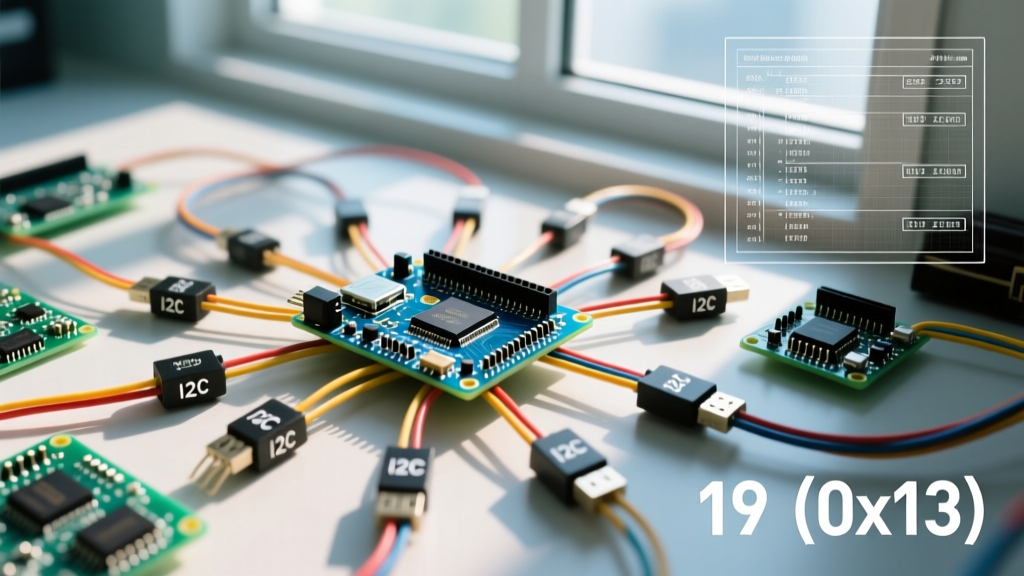

19 hexadecimal (written as 0x19) is the base-16 representation of the decimal number 25, functioning in embedded electronics primarily as the 7-bit I2C bus address for widely used MEMS motion sensors like the STMicroelectronics LIS3DH. In a real circuit, this address changes the physical routing of the I2C start-condition byte, dictating exactly how your microcontroller directs data packets on the SDA and SCL lines to talk to a specific peripheral without colliding with other devices on the bus. The most common point of confusion for makers is mixing up the 7-bit address (0x19) with its 8-bit shifted equivalents (0x32 for write, 0x33 for read), or mistakenly assuming the sensor is listening at decimal 19.
The Math Behind 0x19 (Hex to Decimal to Binary)
To communicate reliably with digital sensors, you need to understand how the microcontroller translates the hex value into physical voltage pulses. Hexadecimal is a base-16 numbering system. To convert 0x19 to decimal, you multiply each digit by 16 raised to the power of its position (starting from 0 on the right):
(1 × 161) + (9 × 160) = 16 + 9 = 25 (Decimal)
In binary, decimal 25 is 0001 1001. However, the I2C protocol defined by NXP's I2C-bus specification uses a 7-bit addressing scheme for standard devices. The 7-bit binary representation of 25 is 001 1001.
Here is where the confusion sets in for Arduino and ESP32 programmers. When the microcontroller actually sends the address over the wire, it shifts that 7-bit value left by one position to make room for the Read/Write (R/W) bit at the end:
- 7-bit Address:
0011001(0x19) - 8-bit Write Address (Shift left + 0):
00110010(0x32 in hex, 50 in decimal) - 8-bit Read Address (Shift left + 1):
00110011(0x33 in hex, 51 in decimal)
If you are using the standard Arduino Wire.h library, the library handles this shift for you. You pass 0x19 to Wire.beginTransmission(). But if you are writing raw register commands or using a logic analyzer to debug the SDA line, you will physically see 0x32 and 0x33 on the bus.
Where You Meet 0x19 in Practice: I2C Sensor Addressing
You will almost exclusively encounter 0x19 when wiring 3-axis accelerometers and IMUs (Inertial Measurement Units) to a microcontroller. The STMicroelectronics LIS3DH, LIS2DH12, and several Bosch sensors default to this address. Think of the I2C address like a postal zip code; the SDA/SCL lines are the highway, and 0x19 ensures the data packet is delivered to the motion sensor rather than the OLED display sitting on the same bus.
Most MEMS sensor breakout boards feature a pin labeled
SDO (Serial Data Out) or SA0 (Slave Address 0). This pin acts as a hardware jumper for the least significant bit of the I2C address.• Tie SDO to GND: The address becomes
0x18 (Decimal 24).• Tie SDO to VCC (3.3V): The address becomes
0x19 (Decimal 25).Never leave the SDO pin floating. A floating pin will cause the sensor to randomly switch between 0x18 and 0x19 due to electromagnetic noise, resulting in intermittent I2C bus lockups.
When you first power up a fresh LIS3DH breakout board, the SDO pin is usually pulled high via an internal or onboard external resistor, making 0x19 the default out-of-the-box address. You can verify this by running an I2C scanner sketch on your ESP32; the serial monitor should report a device found at 0x19.
Decision Path: Configuring Your 0x19 Sensor Circuit
When designing a PCB or wiring a breadboard prototype, you must decide how to handle the sensor's address based on your project's hardware requirements. Use the decision tree below to select the correct wiring topology.
| Scenario / Requirement | If This Is True... | Then Take This Action (Concrete Pick) |
|---|---|---|
| Single Sensor Setup | You only have one LIS3DH/LIS2DH12 on the I2C bus. | Leave SDO tied to VCC. Initialize your code with address 0x19. |
| Dual Sensor Setup | You need two identical sensors on the same SDA/SCL lines (e.g., dual-IMU motion tracking). | Tie Sensor A's SDO to GND (0x18) and Sensor B's SDO to VCC (0x19). |
| Multi-Sensor Array (>2) | You need three or more sensors that share the 0x19/0x18 address space. |
Buy and wire a Texas Instruments TCA9548A I2C Multiplexer. Route each sensor to a separate mux channel. |
| Address Collision | Another critical component (like a specific OLED driver) is hardwired to 0x19 and cannot be changed. |
Use a software I2C library (like SoftwareWire) to bit-bang a secondary I2C bus on different GPIO pins for the sensor. |
Troubleshooting 0x19 I2C Collisions and Ghosting
If your I2C scanner finds 0x19 but your sensor library fails to read acceleration data, or if the bus locks up entirely, the issue is rarely the hex math itself. It is almost always a physical layer violation. Here is how to diagnose it with a multimeter and oscilloscope.
1. Verify Pull-Up Resistor Values
The I2C bus uses open-drain outputs. The microcontroller pulls the line low, but relies on pull-up resistors to bring it back high. If you have multiple sensors on the bus, the parallel resistance drops.
- Standard Mode (100 kHz): Requires ~4.7 kΩ pull-ups to 3.3V.
- Fast Mode (400 kHz): Requires ~2.2 kΩ pull-ups to 3.3V.
Measurement: With the system powered but idle, measure the voltage between SDA and GND. It should read a stable 3.2V to 3.3V. If it reads below 2.8V, your pull-ups are too weak, or a device is actively dragging the line low due to a logic fault.
2. Logic Level Shifting (The 5V vs 3.3V Trap)
Most modern MEMS sensors operating at 0x19 are strictly 3.3V logic devices. If you connect an Arduino Uno (5V logic) directly to the SDA/SCL pins of a LIS3DH without a bidirectional logic level shifter (like the BSS138-based Adafruit 4-channel shifter), you will exceed the maximum VIH (Input High Voltage) rating. This won't immediately fry the chip, but it will cause the internal I2C state machine to lock up, resulting in an ACK failure when the microcontroller tries to ping 0x19.
3. Reading the WHO_AM_I Register
Before trusting a third-party Arduino library, verify you are actually talking to the sensor. According to the STMicroelectronics LIS3DH datasheet, register 0x0F is the WHO_AM_I register. Write 0x0F to the device at 0x19, then request one byte. If the sensor is healthy and wired correctly, it will return 0x33 (Hex). If it returns 0x00 or 0xFF, your wiring or pull-ups are faulty.
Frequently Asked Questions
Why does my logic analyzer show 0x32 when my code says 0x19?
Your code uses the 7-bit logical address (0x19). The logic analyzer captures the physical 8-bit byte on the wire, which includes the Read/Write bit. 0x32 is simply 0x19 shifted left by one bit with a '0' appended for a Write operation.
Can I change the 0x19 address in software?
No. The base I2C address of MEMS sensors is hardcoded in the silicon mask during manufacturing. You can only toggle the least significant bit (between 0x18 and 0x19) using the physical SDO/SA0 pin. To change it further, you must use an I2C multiplexer like the TCA9548A.
Is 0x19 the same as decimal 19?
No. Hexadecimal 19 equals decimal 25. Decimal 19 equals hexadecimal 0x13. Passing the literal integer 19 into an Arduino Wire.beginTransmission() function will target decimal 19 (0x13), which is usually an unused address on the bus, resulting in a silent failure and no data returned.


