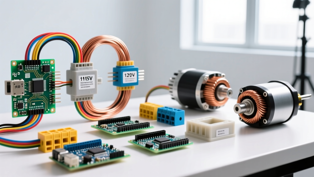

The Verdict: Which Voltage Standard Wins?
For general-purpose North American electrical design, 120V is the undisputed standard for utility delivery, branch circuit wiring, and residential receptacles. However, 115V wins exclusively for motor nameplate ratings and long-run wire sizing calculations, where accounting for voltage drop is a mathematical necessity rather than a theoretical ideal. They describe the exact same physical power grid, but the 6-volt delta separates the utility's delivery target from the appliance's worst-case operating reality.
- Choose 120V when: Wiring standard residential or commercial branch circuits, selecting general-purpose breakers and receptacles (NEMA 5-15), calculating loads for resistive heating elements, or determining transformer secondary outputs.
- Choose 115V when: Sizing conductors for inductive motor loads on long runs, setting thermal overload relays for HVAC compressors, matching legacy industrial control transformers, or calculating worst-case voltage drop to prevent equipment overheating.
The Single Physical Difference: Voltage Drop Under Load
The entire 115 volt vs 120 volt distinction boils down to a single physical phenomenon: voltage drop across conductor resistance under load. A utility's center-tapped split-phase transformer outputs exactly 120V (nominal) at the secondary lugs. But copper and aluminum wire possess inherent resistance. As current flows through a branch circuit, voltage is consumed by the wire itself before it reaches the load.
Consider a 15A load on a 100-foot run of 14 AWG copper wire. Using the standard single-phase voltage drop formula ($V_{drop} = \frac{2 \times K \times I \times D}{CM}$, where $K \approx 12.9$ for copper and $CM = 4110$ for 14 AWG):
$V_{drop} = \frac{2 \times 12.9 \times 15 \times 100}{4110} = 9.4V$
The voltage at the receptacle is now 110.6V. This is a critical failure point for inductive loads. Unlike resistive heaters that simply output less heat at lower voltages, AC motors draw more current when voltage drops to maintain their mechanical power output ($P = V \times I$). This excess current generates severe heat in the motor windings, leading to insulation breakdown and premature failure. To protect against this, motor manufacturers rate their equipment at 115V. This ensures the motor's internal thermal overloads and the circuit's wire sizing are calculated based on the lowest expected operating voltage at the end of a long run, not the ideal 120V at the panel.
| Measurement Point | Minimum Voltage | Maximum Voltage | Standard / Guideline |
|---|---|---|---|
| Utility Service Entrance | 114.0V | 126.0V | ANSI C84.1 Range A |
| Utilization Equipment (Normal) | 114.0V | 126.0V | ANSI C84.1 Range A |
| Utilization Equipment (Extreme) | 110.0V | 127.0V | ANSI C84.1 Range B |
| NEC Recommended Max Drop (Branch) | 116.4V (3% drop) | 120.0V | NEC 210.19(A) Info Note |
| Motor Nameplate Rating | 115.0V | N/A | NEMA MG-1 Standard |
Source: NEMA / ANSI C84.1 Voltage Ratings and NFPA 70 (NEC).
115 Volt vs 120 Volt: Head-to-Head Specification Comparison
While they share the same physical infrastructure, treating 115V and 120V as identical synonyms in engineering calculations leads to undersized wires and tripped breakers. Here is how the two designations diverge in practical application.
| Criteria | 120V Designation | 115V Designation |
|---|---|---|
| System Definition | Nominal utility delivery and panel bus voltage. | Minimum utilization voltage at the load terminals. |
| Primary Application | Branch circuit wiring, breaker sizing, lighting layouts. | Motor nameplates, overload relay settings, long-run wire sizing. |
| Wire Sizing Basis | Calculated using 120V to determine maximum allowable 3% drop (3.6V). | Calculated using 115V to ensure motor starting torque and thermal limits. |
| Standard NEMA Config | NEMA 5-15R (Standard 15A duplex receptacle). | Hardwired motor terminals or NEMA L5-15 (Twist-lock for industrial). |
| Load Type Association | Resistive (heaters, incandescent) and electronic (SMPS power supplies). | Inductive (compressors, fans, pumps, conveyors). |
Where 115V and 120V Are NOT Interchangeable
In a standard home, plugging a '115V' window AC unit into a '120V' wall outlet works perfectly because the physical grid is the same. However, in commercial, industrial, and precision environments, mixing these designations causes catastrophic failures.
In older industrial facilities, you may encounter a 120V 3-phase Wye system (120V line-to-neutral, 208V line-to-line). Do not confuse this with legacy 115V 3-phase Delta systems. Plugging a 115V Delta-rated motor control circuit into a 120V Wye supply will overvolt the control transformer by roughly 4.3%, accelerating insulation degradation and causing premature contactor coil burnout.
Precision Lab and Medical Equipment: Devices like analytical centrifuges or mass spectrometers often specify strict 120V/60Hz input requirements with tight tolerances (e.g., ±2%). If an installer uses a step-down transformer to deliver exactly 115V to 'protect' the device, the internal switched-mode power supplies may fail to regulate correctly, or the equipment's internal cooling fans may spin too slowly, triggering thermal shutdowns.
Control Circuit Transformers: Industrial machine tools use control transformers to step down 480V to 120V for the PLC and pushbuttons. If the machine builder designed the logic circuit assuming a 115V worst-case drop, but the facility's utility supply is running hot at 126V (the top of ANSI Range A), the control voltage could reach 122V. This 6% overvoltage on a 115V-rated relay coil will cause it to draw excess holding current, overheat, and eventually weld its contacts shut—a severe safety hazard.
Cost, Availability, and Hardware Realities
Because 120V is the universal standard for North American infrastructure, hardware designed for the 120V nominal ecosystem benefits from massive economies of scale. 115V-specific hardware is relegated to specialized industrial catalogs and carries a premium.
- Receptacles and Plugs: A standard 120V NEMA 5-15R duplex receptacle (e.g., Leviton 5262) costs between $1.20 and $2.50 at any hardware store. A 115V-rated industrial twist-lock (NEMA L5-15R, like the Hubbell HBL2310) costs $35 to $55, requiring specialized inventory.
- Circuit Breakers: A standard 120V 20A single-pole breaker (Square D HOM120) retails for roughly $6.00. Finding a breaker specifically calibrated for 115V trip curves is unnecessary for standard panels, but specialized 115V DC-rated breakers for telecom or solar battery banks (like the MidNite Solar MNEPV) cost upwards of $45 each.
- Wire Sizing Economics: Designing a circuit using 120V nominal math might allow you to use 12 AWG THHN wire ($0.18/ft). Designing that same run for a 115V motor load to maintain starting torque might force you to upsize to 10 AWG THHN ($0.30/ft) to mitigate voltage drop. On a 200-foot run, that engineering decision adds roughly $24 in copper costs alone, not counting the larger conduit and terminations required.
Ultimately, understanding the 115 volt vs 120 volt distinction separates amateur wire-pullers from competent electrical designers. You deliver 120V from the panel, but you engineer the load to survive on 115V.