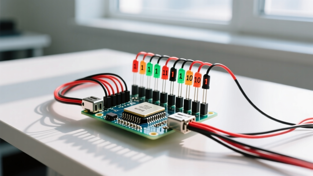

Binary is a base-2 numeral system using only 0s and 1s to represent values, where the decimal numbers 1 to 10 are written as 0001 through 1010. If you need the exact 4-bit binary equivalents for the decimal integers 1 through 10, they are: 0001, 0010, 0011, 0100, 0101, 0110, 0111, 1000, 1001, and 1010. While this sequence is elementary in abstract math, on the workbench, these specific 4-bit patterns dictate physical voltage states on microcontroller pins, shift register outputs, and digital logic gates.
The Core Mechanism: How Base-2 Counts to Ten
In a 4-bit binary system, each position represents a power of two, starting from the right (Least Significant Bit, or LSB) and moving left to the Most Significant Bit (MSB). The weights are 8, 4, 2, and 1. To represent any decimal number from 1 to 10, you simply add the weights of the positions that hold a '1'.
0111. If this 4-bit value is written to a 4-pin GPIO port configured as outputs, Pin 3 reads 0V (LOW), while Pins 2, 1, and 0 read 3.3V (HIGH).
| Decimal | Binary (4-Bit) | Hexadecimal | GPIO Pin States (3.3V Logic) |
|---|---|---|---|
| 1 | 0001 | 0x01 | LOW, LOW, LOW, HIGH |
| 2 | 0010 | 0x02 | LOW, LOW, HIGH, LOW |
| 3 | 0011 | 0x03 | LOW, LOW, HIGH, HIGH |
| 4 | 0100 | 0x04 | LOW, HIGH, LOW, LOW |
| 5 | 0101 | 0x05 | LOW, HIGH, LOW, HIGH |
| 6 | 0110 | 0x06 | LOW, HIGH, HIGH, LOW |
| 7 | 0111 | 0x07 | LOW, HIGH, HIGH, HIGH |
| 8 | 1000 | 0x08 | HIGH, LOW, LOW, LOW |
| 9 | 1001 | 0x09 | HIGH, LOW, LOW, HIGH |
| 10 | 1010 | 0x0A | HIGH, LOW, HIGH, LOW |
Where You Meet This in Practice: GPIO and Shift Registers
Understanding 1 to 10 binary numbers changes how you interact with physical hardware. When you write a binary number to a microcontroller's port register—such as the GPIO_OUT_REG on an ESP32-WROOM-32—you are not just doing math; you are physically altering silicon. A '1' in the register turns on the high-side MOSFET in the GPIO pad, driving the physical pin to VCC (e.g., 3.3V). A '0' turns on the low-side MOSFET, pulling the pin to GND (0V).
This mapping is critical when driving external digital logic. For instance, if you are using a 4-bit resistor ladder DAC (Digital-to-Analog Converter) built from precision resistors, feeding it the binary sequence from 0001 to 1010 will output 10 distinct, evenly spaced analog voltage steps between 0V and your reference voltage. Similarly, when addressing I2C peripherals, many sensors have base addresses that require you to append a 4-bit binary suffix to select a specific device on the bus.
Real-World Scenario Walkthrough: Debugging a 74HC595 Shift Register
Theory often breaks down when wiring meets code. Here is a common bench scenario where misinterpreting binary bit-ordering causes hardware failure.
- The Setup: You are driving a 4-LED indicator array using a 74HC595 shift register controlled by an Arduino Nano. You want to display the number 10, which is
1010in binary. You wire the shift register's QA output to LED 1 (MSB), QB to LED 2, QC to LED 3, and QD to LED 4 (LSB). - The Code: You call
shiftOut(dataPin, clockPin, MSBFIRST, 10);expecting the LEDs to read ON-OFF-ON-OFF. - The Outcome: The LEDs light up as OFF-ON-OFF-ON (binary
0101, decimal 5). The circuit works, but the displayed value is inverted. - What Went Wrong: The 74HC595 shifts data into its internal register starting at QA. When you specify
MSBFIRST, the Arduino sends the MSB (the left-most '1' in 1010) first, which lands in QA. However, because QA is physically wired to your MSB LED, the bit order is reversed relative to your visual expectation. The shift register essentially mirrored your binary number. - The Fix: Either change the code to
LSBFIRSTso the bits shift into the register in reverse order, or physically rewire the LEDs so that QD (the last bit shifted in) connects to your visual MSB position.
Common Confusions: Binary vs. BCD and Hexadecimal
When working with digital displays and thumbwheel switches, makers frequently confuse pure binary with Binary Coded Decimal (BCD) and Hexadecimal.
- Pure Binary vs. BCD: In pure binary, the decimal number 10 is
1010. In BCD, each decimal digit is encoded separately into a 4-bit nibble. Therefore, decimal 10 in BCD is0001 0000(a '1' nibble followed by a '0' nibble). If you feed pure binary1010into a BCD-to-7-segment decoder like the CD4511, the chip will interpret it as an invalid state (since BCD only recognizes 0000 to 1001) and blank the display. - Binary vs. Hexadecimal: Beginners often see
10in a hex dump and assume it means decimal ten. In hexadecimal,10equals decimal 16 (binary10000). The decimal number 10 is represented as0Ain hex. Always check the prefix:0b10is binary (decimal 2),0x10is hex (decimal 16), and10without a prefix is usually decimal.
FAQ: Binary Counting in Embedded Systems
Why do we use 4 bits to represent numbers up to 10?
Three bits can only count up to 7 (binary 111). To reach decimal 8, 9, and 10, you must cross the threshold into the fourth bit (weights of 8). Therefore, any hardware register, DIP switch bank, or logic array intended to handle values from 1 to 10 must be at least 4 bits wide, giving it a maximum capacity of 15 (binary 1111).
How do I verify binary states on a physical circuit without an oscilloscope?
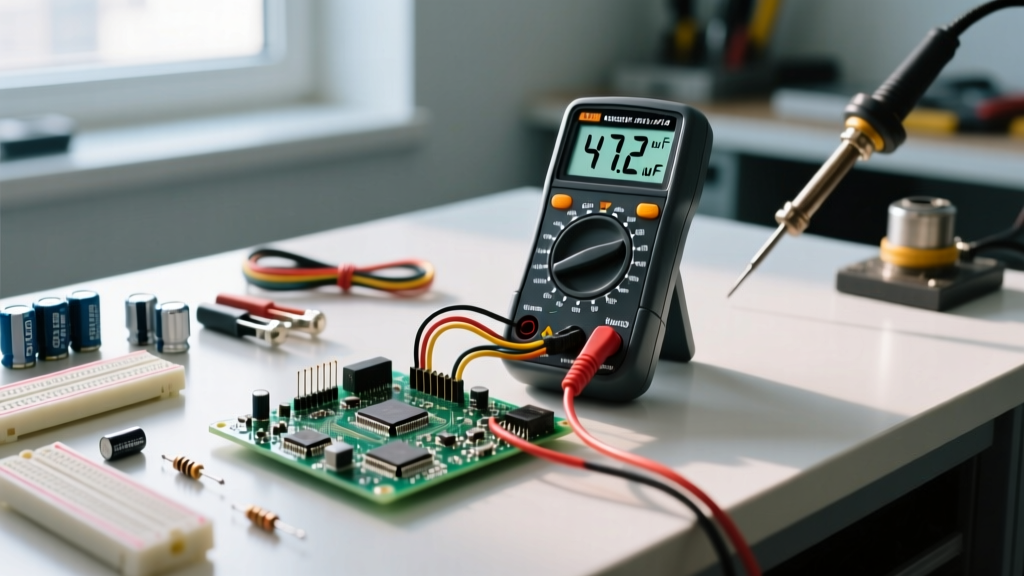
If you don't have a logic analyzer or scope, use a standard digital multimeter (DMM) set to DC Voltage. Measure between the GPIO pin and the system GND. For a 3.3V microcontroller, a binary '1' will read between 3.2V and 3.3V, while a binary '0' will read between 0.0V and 0.1V. If you read an intermediate voltage (e.g., 1.6V), the pin is likely floating, misconfigured as an input, or being actively driven by a PWM signal rather than a static binary state.
Does the binary sequence change for negative numbers?
Yes, if you are using signed integers. Microcontrollers typically use Two's Complement for negative numbers. However, for standard GPIO outputs and shift registers, the hardware treats the bits as unsigned. Writing a signed negative integer to a GPIO register will simply output the raw Two's Complement bit pattern as physical HIGH/LOW voltages, which is rarely what you intend for physical logic control.