
Bridging Physics and the Workbench: The Electric Charge Definition
When electrical technicians and electronics engineers encounter erratic system behavior, the root cause almost always traces back to a fundamental misunderstanding of how charge accumulates, moves, and equalizes. At its core, the electric charge definition in physics describes a fundamental property of matter that causes it to experience a force when placed in an electromagnetic field. Measured in Coulombs (C), the elementary charge of a single electron is approximately -1.602 × 10⁻¹⁹ C, as defined by the NIST SI unit standards.
While textbook definitions focus on subatomic particles, practical troubleshooting requires us to look at electric charge macroscopically. In wiring, microcontrollers, and industrial motors, charge does not simply 'exist'—it couples, accumulates, and violently equalizes when given the chance. By viewing diagnostic anomalies through the lens of charge accumulation versus charge flow (current), we can solve some of the most frustrating 'ghost' faults in modern electrical systems.
Static vs. Dynamic Charge: Why Multimeters Lie to You
The most common diagnostic error in residential and commercial wiring is misinterpreting capacitive coupling as a live circuit. This phenomenon is entirely governed by the behavior of static electric charge. When an energized 120V AC wire runs parallel to a de-energized (disconnected) wire inside the same conduit, the insulation between them acts as a dielectric. This creates a parasitic capacitor.
The High-Impedance Multimeter Trap
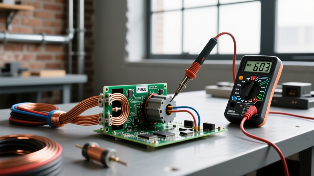
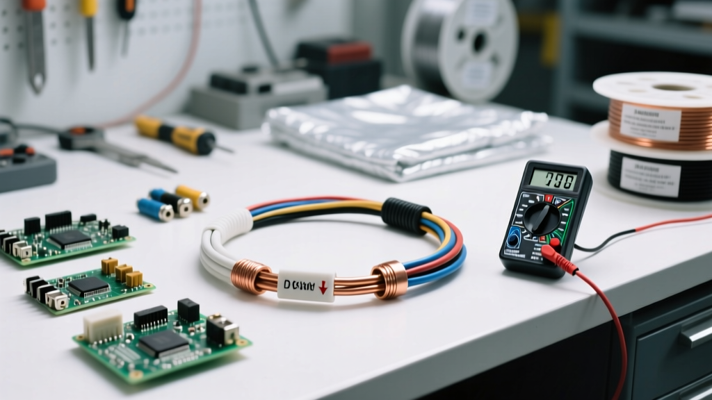
Modern digital multimeters (DMMs) like the Fluke 87V possess an input impedance of roughly 10 Megohms (MΩ). Because they draw almost zero current, they are highly sensitive to minute amounts of coupled electric charge. When you probe the dead wire, the DMM completes the capacitive circuit, allowing the tiny accumulated charge to deflect the meter's internal circuitry, often displaying a 'ghost voltage' between 40V and 90V. Inexperienced technicians may assume the circuit is still hot or that a breaker has failed, leading to unnecessary and dangerous teardowns.
Expert Diagnostic Tip: Never trust a high-impedance reading on an unverified open circuit. If your DMM reads 68V on a wire you believe is disconnected, switch to a solenoid tester (Wiggy) or a meter with a LoZ (Low Impedance) mode. A LoZ mode drops the internal resistance to roughly 3 kΩ, intentionally bleeding off the stray capacitive charge and revealing the true 0V state.
For a deeper dive into how high-impedance inputs create false positives, the Fluke Corporation's guide on ghost voltages provides excellent field schematics demonstrating this exact charge-coupling behavior.
Troubleshooting Framework: Charge Symptom Matrix
To systematically eliminate charge-related diagnostic errors, use the following matrix to cross-reference your symptoms with the underlying physics of the electric charge.
| Field Symptom | Measured Value | Root Cause (Charge Behavior) | Diagnostic Fix & Tooling |
|---|---|---|---|
| Ghost Voltage on dead circuit | 40V - 90V AC | Capacitive coupling inducing stray charge across wire insulation dielectric. | Use LoZ (Low Impedance) DMM mode or solenoid tester to bleed charge. |
| Premature motor bearing failure (fluting) | High dv/dt noise on scope | Rotor charge accumulation seeking ground through bearing grease. | Install AEGIS shaft grounding ring; verify with oscilloscope. |
| Random MCU resets or dead GPIO pins | N/A (Catastrophic failure) | Triboelectric static charge discharge (ESD) breaching gate oxide. | Implement TVS diodes, verify ESD mat grounding to < 1.0 x 10⁹ Ω. |
| Shocks from appliance chassis | Microamp leakage | Y-capacitor filter charge accumulating on ungrounded floating chassis. | Verify equipment grounding conductor (EGC) continuity. |
Real-World Case Study: VFD Motor Bearing Pitting
One of the most destructive manifestations of unmanaged electric charge occurs in industrial settings involving Variable Frequency Drives (VFDs). VFDs synthesize AC waveforms using high-frequency Pulse Width Modulation (PWM). The rapid switching creates a high dv/dt (change in voltage over time), which induces a common-mode voltage on the motor stator.
Through parasitic capacitance between the stator and the rotor, an electric charge builds up on the motor shaft. Because the shaft is spinning on a film of dielectric lubricant (bearing grease), the charge has no immediate path to ground. Once the accumulated charge exceeds the dielectric breakdown voltage of the grease (typically around 15 to 30 peak volts), it violently discharges through the bearings to the grounded motor housing. This process, known as Electrical Discharge Machining (EDM), vaporizes microscopic craters into the bearing races, resulting in a 'fluting' pattern and catastrophic mechanical failure within months.
Troubleshooting Shaft Voltage
You cannot measure this charge accumulation with a standard multimeter. Troubleshooting requires an oscilloscope with a high-bandwidth differential probe or a specialized shaft voltage probe. If you measure peak-to-peak shaft voltages exceeding 15V, the electric charge is not being safely diverted. The mandatory corrective action is the installation of a conductive microfiber shaft grounding ring (such as an AEGIS SGR) to provide a continuous, zero-resistance path for the charge to equalize with the earth ground, bypassing the bearings entirely.
ESD and Microcontrollers: The Human Body Model
In electronics DIY and PCB repair, the electric charge definition takes on a tactile form: Electrostatic Discharge (ESD). The triboelectric effect causes electrons to transfer between materials upon contact and separation. Simply walking across a carpeted room in rubber-soled shoes can cause your body to accumulate an electric charge equivalent to 10,000V or more.
While the total energy (Joules) is low, the voltage potential is massive. When you reach out to touch a bare microcontroller—such as an ATmega328P or an STM32 development board—that accumulated charge seeks the lowest impedance path to ground. If it enters through a GPIO pin, it can instantly puncture the nanometer-thin silicon dioxide gate insulation inside the IC. The component may fail immediately (dead short) or suffer latent damage, leading to erratic logic faults weeks later.
According to the ESD Association, proper troubleshooting of ESD-sensitive environments requires verifying that your workstation's dissipative mats and wrist straps are not just connected to a wire, but are actively bleeding charge to a verified earth ground with a resistance typically between 750 kΩ and 35 MΩ. This specific resistance range ensures that hazardous static charge is safely neutralized without creating an electrocution hazard if you accidentally touch a live 120V/240V source while grounded.
Summary: Respecting the Charge
Whether you are chasing a 70V ghost reading in a residential switch box, diagnosing a fluted bearing on a 50HP inverter-duty motor, or wondering why your custom PCB keeps resetting, the physics remain identical. Electric charge will always accumulate on isolated conductors and will always violently equalize when the dielectric threshold is breached. By upgrading your diagnostic toolkit to include LoZ meters, oscilloscopes, and proper grounding frameworks, you stop fighting the symptoms and start managing the fundamental physics of the circuit.