
The Complexity of Alternating Current AC Diagnostics
Troubleshooting direct current (DC) circuits is largely a matter of verifying continuity, resistance, and steady-state voltage. However, when troubleshooting alternating current AC systems, electrical professionals must contend with a dynamic environment defined by frequency, phase angles, power factor, and waveform distortion. Unlike DC, AC voltage and current are continuously changing magnitude and direction, typically following a sinusoidal path at 50 Hz or 60 Hz.
Modern electrical grids and facility wiring are no longer populated by simple resistive loads like incandescent bulbs or heating elements. The proliferation of non-linear loads—such as Variable Frequency Drives (VFDs), switched-mode power supplies (SMPS), and LED drivers—has fundamentally altered the AC waveform. This guide provides a deep-dive, expert-level framework for diagnosing and resolving complex AC faults, moving beyond basic multimeter checks into power quality analysis.
Why True-RMS is Non-Negotiable for AC Troubleshooting
The most common mistake junior technicians make when diagnosing AC circuits is relying on averaging multimeters. An averaging meter assumes a perfect sine wave and calculates the Root Mean Square (RMS) value by applying a fixed mathematical multiplier to the rectified average.
When non-linear loads chop the AC waveform, creating flat-tops or severe distortion, an averaging meter can read up to 20% to 30% lower than the actual heating value of the circuit. To accurately troubleshoot alternating current AC faults, you must use a True-RMS multimeter or a power quality analyzer. True-RMS instruments sample the waveform thousands of times per second, squaring the instantaneous values, averaging them, and taking the square root, thereby capturing the true thermal energy delivered to the load regardless of waveform distortion.
Diagnostic Framework: A Systematic Approach to AC Faults
Effective troubleshooting requires a structured methodology to isolate the fault without risking arc flash incidents or misdiagnosing secondary symptoms as primary failures.
Phase 1: Source Verification and Voltage Drop Analysis
Before inspecting the load, verify the source. Measure the AC voltage at the main distribution panel under full load conditions. A reading of 120V at the panel that drops to 108V at the receptacle indicates an undersized conductor, loose termination, or excessive circuit length. In AC systems, voltage drop is not purely resistive; it is impedance-based. The inductive reactance of the cable plays a massive role, especially in large-gauge wires routed through steel conduit. Use the formula Vd = I x (R cosθ + X sinθ) x L to calculate single-phase AC voltage drop, factoring in the load's power factor (cosθ).
Phase 2: Identifying Harmonic Distortion and Neutral Overloading
If a facility experiences overheating neutral wires despite balanced phase currents, you are likely dealing with triplen harmonics (3rd, 9th, 15th). In a three-phase wye system, fundamental currents (60 Hz) cancel out in the neutral. However, triplen harmonics are zero-sequence currents; they do not cancel but instead add arithmetically in the neutral conductor. This can cause the neutral current to exceed the phase current by up to 173%, leading to catastrophic insulation failure. Use a power quality analyzer like the Fluke 435 to measure Total Harmonic Distortion (THD). If THD exceeds 5% for voltage or 20% for current, you must install K-rated transformers or active harmonic filters.
Phase 3: Evaluating Transients and Zero-Crossing Anomalies
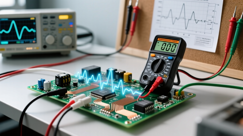
Intermittent equipment resets or unexplained PLC faults are often caused by AC transients—microsecond spikes in voltage triggered by inductive load switching (e.g., contactors opening) or capacitor bank energization. Standard multimeters cannot capture these events. You must deploy an oscilloscope or a power logger equipped with transient capture capabilities, set to trigger on voltage spikes exceeding 1.5 times the nominal peak voltage (e.g., spikes over 254V on a 120V RMS system).
AC Troubleshooting Matrix: Symptoms to Solutions
| Observed Symptom | Probable Root Cause | Diagnostic Tool & Action | Resolution Strategy |
|---|---|---|---|
| Overheating neutral conductor; burning smell at panel. | Triplen harmonics from non-linear loads (SMPS, LED drivers). | Power Quality Analyzer: Log neutral current vs. phase current and measure THD. | Upsize neutral conductor to 200% capacity; install active harmonic filters or K-rated transformers. |
| Motor runs hot, efficiency drops, breaker trips randomly. | Voltage unbalance or excessive voltage distortion (flat-topping). | True-RMS Multimeter: Measure phase-to-phase voltage on all three legs. Calculate NEMA unbalance percentage. | Balance single-phase loads across the three-phase panel; check for degraded power factor correction capacitors. |
| Sensitive electronics reboot intermittently. | AC voltage sags (brownouts) or microsecond switching transients. | Power Logger: Set to capture RMS voltage cycles and transient spikes over a 7-day period. | Install online double-conversion UPS systems; add transient voltage surge suppressors (TVSS) at the panel. |
| Measured voltage is correct, but equipment lacks torque/power. | Poor Power Factor (high reactive power) or incorrect frequency. | Power Analyzer: Measure kW, kVAR, and Power Factor (PF). Verify Hz. | Install automatic capacitor banks to correct PF; check utility supply for frequency deviations. |
The Impact of Skin Effect in AC Conductor Sizing
A frequently overlooked aspect of troubleshooting alternating current AC systems—particularly in heavy industrial environments—is the skin effect. Unlike DC, where current flows uniformly across the entire cross-section of a conductor, AC current tends to migrate toward the outer surface (the 'skin') of the wire. This effect is exacerbated as frequency increases and conductor diameter grows.
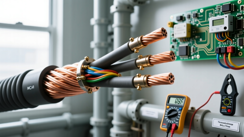
At 60 Hz, the skin effect is negligible for wire gauges smaller than 2/0 AWG. However, for large feeders (e.g., 500 kcmil or larger), the effective resistance of the AC conductor is significantly higher than its DC resistance. If a technician is troubleshooting an unexpected voltage drop on a large feeder and uses standard DC resistance tables to calculate the expected drop, they will miscalculate the fault. The NEC (NFPA 70) Chapter 9, Table 9 provides specific AC resistance and reactance values for conductors in steel, aluminum, and PVC conduits to account for this exact phenomenon. Always use AC impedance values, not DC resistance, when troubleshooting large-gauge AC feeders.
Safety Protocols: Respecting the Arc Flash Boundary
Troubleshooting live AC circuits carries severe risks of arc flash and electrocution. The energy released during an AC fault is sustained by the utility grid, making it vastly more destructive than a localized DC battery fault.
Critical Safety Rule: Never use a CAT II rated multimeter to probe a main distribution panel. According to ESFI and NFPA 70E guidelines, probing a 480V three-phase AC panel requires a minimum CAT III 1000V or CAT IV 600V rated instrument to ensure the internal blast shield and high-energy fuses can withstand a transient arc flash event.
Always wear appropriately rated Personal Protective Equipment (PPE), establish an arc flash boundary based on the available fault current calculated at the specific busbar, and utilize non-contact voltage detectors (NCVD) rated for the specific AC frequency and voltage class before making direct metal-to-metal contact with test probes.
Conclusion: Moving Beyond the Sine Wave
Mastering the troubleshooting of alternating current AC circuits requires shifting your mindset from simple continuity checks to comprehensive power quality analysis. By understanding the thermal realities of True-RMS, the destructive nature of triplen harmonics, and the physical limitations imposed by the skin effect, electrical professionals can accurately diagnose complex faults that standard testing procedures miss. Invest in high-quality diagnostic equipment, adhere strictly to NFPA 70E safety boundaries, and always analyze the AC waveform in its entirety.