
The Anatomy of a TFT LCD Display Module Failure
Integrating a TFT LCD display module into an embedded project should be a straightforward process, yet it remains one of the most common stumbling blocks for DIY electronics enthusiasts and professional engineers alike. Whether you are working with a 2.8-inch ILI9341, a 1.3-inch IPS ST7789, or a compact ST7735, these displays rely on high-speed serial communication and precise initialization sequences. When a display fails to render graphics, the root cause is rarely a defective panel; it is almost always a mismatch in logic levels, SPI bus contention, or incorrect Memory Access Control (MADCTL) register configuration.
This comprehensive troubleshooting guide bypasses generic advice and dives deep into the electrical and software-level diagnostics required to resurrect a stubborn TFT LCD display module. We will cover hardware verification, SPI clock tuning, and register-level debugging to get your project rendering smoothly.
Symptom 1: The 'White Screen' or Completely Blank Display
The infamous 'White Screen of Death' (or occasionally a solid black screen, depending on the panel's default unpowered state) indicates that the display's backlight is receiving power, but the display controller has not successfully received or executed the initialization command sequence. The microcontroller is failing to handshake with the TFT driver IC.
The 5V vs 3.3V Logic Level Mismatch
The most frequent culprit in Arduino-based projects is logic level incompatibility. Most modern TFT LCD display modules operate strictly at 3.3V logic. If you connect a 5V microcontroller (like an ATmega328P-based Arduino Uno) directly to the SPI pins (MOSI, SCK, CS, DC), you risk damaging the input buffer of the display controller. Even if the silicon survives, the 5V HIGH signal might exceed the absolute maximum ratings, causing the controller to misinterpret clock edges or lock up entirely during initialization.
The Fix: Implement a bidirectional logic level shifter. A CD4050 hex buffer or a BSS138 MOSFET-based level shifter is mandatory for 5V systems. Ensure the level shifter's high-side reference is tied to 5V and the low-side reference is tied to the display's 3.3V rail. Do not rely on internal clamping diodes or simple resistor voltage dividers for high-speed SPI lines, as the RC time constant created by the resistors and the parasitic capacitance of the breadboard will degrade the square wave into a triangle wave, causing data corruption at speeds above 4 MHz.
Reset (RST) Pin Timing and Floating States
TFT controllers require a highly specific hardware reset sequence before accepting SPI commands. The RST pin must be pulled LOW for at least 10 microseconds, followed by a HIGH state, and then the microcontroller must wait for 120 milliseconds before sending the first SPI byte. If your microcontroller code toggles the RST pin but fails to implement this mandatory delay, the display controller will ignore the initialization payload. Furthermore, if the RST pin is left floating or driven by a noisy source, electromagnetic interference (EMI) from the backlight inverter can trigger spontaneous resets, resulting in screen tearing or blanking.
Symptom 2: Inverted Colors, Mirrored Text, and Offset Graphics
If your display turns on and renders graphics, but the colors are inverted (e.g., black backgrounds appear white, or reds appear blue), or the image is mirrored and pushed off the edge of the glass, you are dealing with a MADCTL (Memory Access Control) register misconfiguration.
Understanding the MADCTL Register (0x36)
The MADCTL register dictates how the display controller's internal RAM maps to the physical LCD glass. Bit 3 of this register controls the RGB/BGR color order. Many generic TFT LCD display modules sourced from overseas marketplaces use BGR panel layouts despite being advertised as RGB. If your reds render as blue, you must flip Bit 3 in your initialization code. For users of the TFT_eSPI Library, this is easily resolved by uncommenting the `#define TFT_BGR` macro in the `User_Setup.h` file.
The Offset Issue (ST7789 Specific): Many 1.3-inch and 1.54-inch ST7789 modules utilize a silicon driver IC capable of addressing a 240x280 pixel matrix, but the physical LCD glass is only 240x240 pixels. This results in a 40-pixel invisible offset. If your graphics appear cut off or shifted, you must apply a software coordinate offset in your graphics library (e.g., `setSwapBytes(true)` and adjusting the X/Y start coordinates in the Adafruit GFX or TFT_eSPI library) rather than attempting to alter the hardware wiring.
Symptom 3: Flickering, Tearing, and SPI Bus Contention
Intermittent flickering, random noise pixels ('snow'), or screen tearing during high-framerate updates points directly to SPI signal integrity issues or bus contention.
Parasitic Capacitance and SPI Clock Dividers
While datasheets for the ILI9341 and ST7789 boast SPI clock speeds up to 60 MHz or 72 MHz, these speeds are only achievable on custom PCBs with controlled impedance and ultra-short trace lengths. When prototyping on a solderless breadboard using standard Dupont jumper wires, the parasitic capacitance between the rows will severely degrade signal integrity at frequencies above 20 MHz. If your display flickers, lower the SPI clock speed. In Arduino environments, adjust the SPI clock divider from `SPI_CLOCK_DIV2` to `SPI_CLOCK_DIV4` or `SPI_CLOCK_DIV8` until the signal stabilizes.
Expert Hardware Tip: Always solder a 10µF tantalum or low-ESR ceramic capacitor directly across the VCC and GND pins on the back of the TFT LCD display module PCB. The sudden current draw when switching thousands of pixels simultaneously can cause micro-brownouts on the 3.3V LDO regulator, leading to spontaneous SPI bus disconnects and screen freezing.
Hardware Verification: Multimeter Diagnostic Matrix
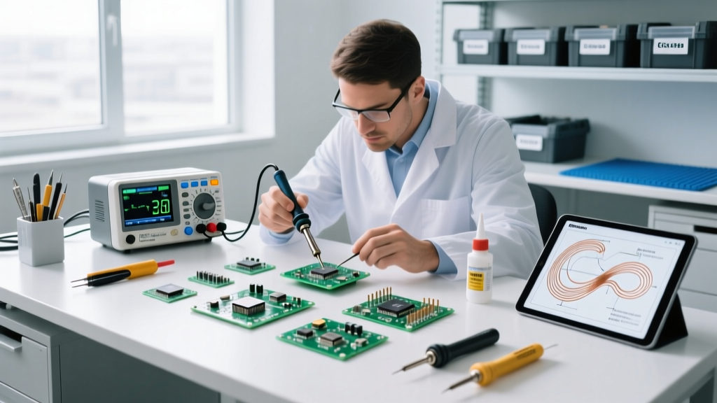
Before rewriting your code, use a digital multimeter (DMM) to verify the physical state of the display module. The following table outlines the expected electrical states for a standard SPI-based TFT LCD display module during idle and active rendering phases.
| Pin / Net | Expected Idle State | Expected Active State | Common Failure Symptom if Incorrect |
|---|---|---|---|
| VCC (3.3V) | 3.25V - 3.35V DC | 3.20V - 3.35V DC | Brownouts, random reboots, white screen. |
| LED (Backlight) | 0V (Off) or 3.3V (On) | 3.3V DC (Steady) | Flickering backlight, dim display (insufficient current from GPIO). |
| CS (Chip Select) | HIGH (3.3V) | Pulsing LOW (0V) | Display ignores commands, SPI bus locks up other peripherals. |
| DC (Data/Command) | HIGH or LOW | Rapidly toggling | Display interprets pixel data as commands, resulting in garbage noise. |
| SCK (Clock) | LOW (Mode 0) or HIGH | Rapid square wave | No display output; DMM reads ~1.6V (average of high-speed toggling). |
Symptom 4: Touch Screen (XPT2046) Misalignment and Drift
Many 2.4-inch and 2.8-inch TFT LCD display modules include a resistive touch overlay driven by the XPT2046 controller. A frequent issue is touch coordinate inversion or severe drift, where touching the top-left registers as the bottom-right.
Resistive touch panels do not possess native coordinate systems; they output raw analog-to-digital (ADC) values representing voltage gradients across the X and Y layers. These raw values (typically ranging from 200 to 3800) must be mapped to the display's pixel coordinates using a calibration matrix. If you replace a display module with a seemingly identical one from a different batch, the physical alignment of the glass to the sensor layer may differ by a few millimeters, rendering your hardcoded calibration matrix obsolete.
The Fix: Run a touch calibration sketch (such as the `TouchScreen_Calib` example in the Adafruit TFT Touch Shield Guide) to generate a new transformation matrix. Furthermore, ensure the XPT2046's SPI Chip Select pin is entirely separate from the TFT's CS pin. Sharing the SPI bus is perfectly fine, but if both CS pins are pulled LOW simultaneously, the touch controller and the display controller will talk over each other, corrupting both the graphics RAM and the touch ADC readings.
Advanced Debugging: Logic Analyzers and Oscilloscopes
When multimeters and code tweaks fail, you must visualize the SPI bus. Using an entry-level logic analyzer (such as a Saleae clone) paired with PulseView or Sigrok is invaluable for debugging TFT LCD display module initialization. Connect the analyzer to SCK, MOSI, CS, and DC.
Decode the SPI traffic and verify that the microcontroller is sending the correct initialization hex arrays. Pay close attention to the SPI Mode. The ILI9341 and ST7789 generally require SPI Mode 0 (CPOL=0, CPHA=0). If your microcontroller is configured for SPI Mode 3, the data will be sampled on the wrong clock edge, resulting in the display controller receiving garbage initialization commands and defaulting to a blank state. For deeper analog signal integrity analysis, referencing the Adafruit ST7789 Guide and the official silicon datasheets will provide the exact timing diagrams required to verify setup and hold times on your oscilloscope.
Conclusion
Troubleshooting a TFT LCD display module requires a systematic elimination of hardware, electrical, and software variables. By respecting 3.3V logic thresholds, managing SPI parasitic capacitance, and correctly configuring the MADCTL registers, you can transform a blank, flickering piece of glass into a vibrant, high-speed interface for your next embedded electronics project.