
Unlocking the Servo in Build a Boat: The Virtual Sandbox
For many aspiring engineers and DIYers, the first encounter with mechanical linkages and rotational logic happens not in a physical lab, but inside the Roblox game Build a Boat for Treasure. If you are searching for how to get servo in build a boat, the in-game answer is straightforward: the Servo block is a specialized mechanical part that allows for hinged, motorized rotation. You can typically obtain it by progressing through specific stages, unlocking it via the Shop using accumulated Gold, or finding it in advanced mechanical chests. Once equipped, it allows players to create steering rudders, flapping hydrofoils, and complex suspension systems.
However, while the game abstracts the physics and electronics into simple click-and-drag blocks, the real-world application of servos in marine engineering and RC boat building is a masterclass in embedded systems, pulse-width modulation, and environmental hardening. Let us pivot from the virtual sandbox to the workbench and explore the actual electronics fundamentals that make marine servo steering possible.
The Engineering Reality: How Marine Servos Actually Work
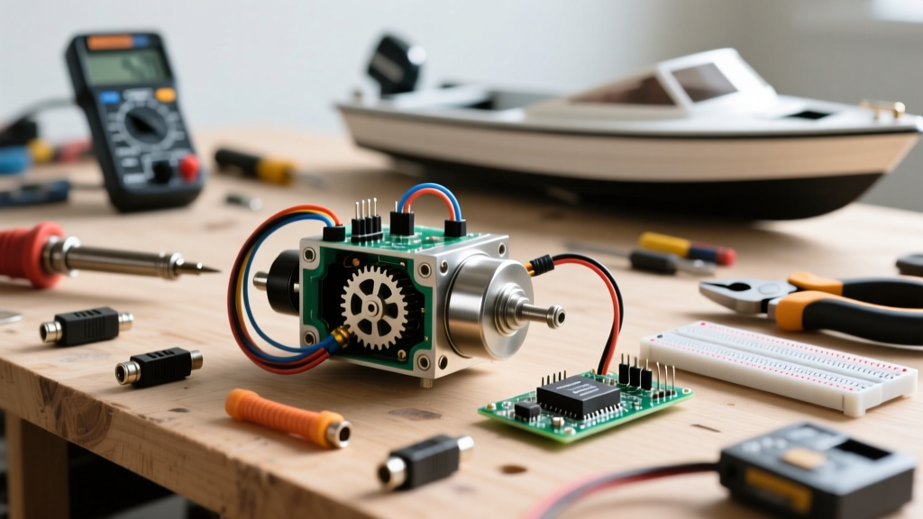
In real-world RC boats, a servo is the muscle responsible for translating low-power microcontroller signals into high-torque mechanical movement. Unlike standard DC motors that spin continuously, a standard positional servo is a closed-loop system designed to move to a specific angle and hold that position against external forces—such as the hydrodynamic drag of water pushing against a boat's rudder.
Inside the Casing: Gears, Motors, and Potentiometers
According to the Adafruit All About Servos guide, a standard RC servo contains three critical components:
- DC Motor: Provides the raw rotational force.
- Gear Train: Reduces the high-speed, low-torque output of the motor into low-speed, high-torque output. Marine servos often use metal (brass or titanium) gears to prevent stripping under heavy water loads.
- Potentiometer: A variable resistor connected to the output shaft. It constantly measures the physical angle of the shaft and feeds this data back to the internal control board, creating a closed-loop feedback system.
Decoding PWM: The Heartbeat of Servo Control
To control a servo, microcontrollers and RC receivers do not send analog voltage levels. Instead, they use Pulse Width Modulation (PWM). The Pololu RC Servo Guide details that standard hobby servos expect a 50Hz signal (one pulse every 20 milliseconds). The width of the high-voltage pulse within that 20ms window dictates the target angle.
The Microsecond Dictionary
| Pulse Width | Target Position | Boat Application |
|---|---|---|
| 1000 µs (1.0 ms) | 0° (Full Left) | Rudder Hard-to-Port |
| 1500 µs (1.5 ms) | 90° (Center) | Rudder Dead Straight |
| 2000 µs (2.0 ms) | 180° (Full Right) | Rudder Hard-to-Starboard |
If the internal potentiometer reads that the shaft is currently at 80°, but the microcontroller sends a 1500 µs pulse (commanding 90°), the internal H-bridge circuit will power the DC motor until the potentiometer reads exactly 90°, then cut the power.
Positional vs. Continuous Rotation: Steering vs. Throttle
When building a physical RC boat, it is vital to distinguish between standard positional servos and continuous rotation servos.
- Standard Positional Servos: Used for steering rudders, trim tabs, and sail winches. They are restricted to a ~180° arc and rely on the potentiometer for absolute position feedback.
- Continuous Rotation Servos: The potentiometer is removed or bypassed. The PWM signal no longer dictates position, but rather speed and direction. A 1500 µs pulse means 'stop', 1000 µs means 'full speed reverse', and 2000 µs means 'full speed forward'. These are occasionally used in DIY surface-drive throttle mechanisms, though dedicated Electronic Speed Controllers (ESCs) are generally preferred for marine propulsion.
Wiring Your First RC Boat Servo to a Microcontroller
If you are using an Arduino or a custom PCB to steer your boat, you must wire the servo correctly. Most hobby servos use a standard 3-pin JR or Futaba connector. As noted in the Arduino Servo Library documentation, the pinout is universally color-coded:
- Ground (GND): Black or Brown wire. Must be tied to the common ground of your microcontroller and power supply.
- Power (VCC): Red wire. Requires 4.8V to 6.0V DC. Never power a high-torque marine servo directly from an Arduino's 5V pin; the current draw during stall conditions can exceed 2 Amps and fry the microcontroller's voltage regulator.
- Signal (PWM): Orange, Yellow, or White wire. Connects to a digital PWM-capable pin on your microcontroller (e.g., Pin 9 on an Arduino Uno).
Expert Marine Tip: Always use a dedicated BEC (Battery Eliminator Circuit) to step down your main LiPo boat battery (e.g., 11.1V or 14.8V) to a clean 6.0V for the servo VCC line. This prevents voltage sags from the main propulsion motor from causing the steering servo to brown out and lose its center position.
Marine-Grade Hardware: Selecting the Right Servo for Watercraft
The virtual servos in Build a Boat never rust or short-circuit. Real-world marine environments are incredibly hostile to electronics. Saltwater, humidity, and constant vibration will destroy a standard hobby servo in a matter of days. When selecting hardware for an RC boat, you must evaluate torque, gear material, and IP ratings.
| Servo Model | Torque (at 6V) | Gear Material | Water Resistance | Best Use Case |
|---|---|---|---|---|
| Tower Pro MG996R | 13.0 kg-cm | Brass/Metal | None (Open Case) | Budget builds, freshwater testing, internal dry-box mounting. |
| Savox SW-1210SG | 10.0 kg-cm | Steel | Water-Resistant (O-Ring) | High-speed RC racing boats, precision rudder control. |
| Hitec HS-5646WP | 8.3 kg-cm | Karbonite | IP67 Waterproof | Scale tugboats, sailboats, exposed deck steering mechanisms. |
| Spektrum S6140 | 16.5 kg-cm | Steel | Waterproof | Large 1/8th scale offshore powerboats requiring massive rudder throw. |
Advanced Troubleshooting: Eliminating Servo Jitter on the Water
When testing your boat, you may notice the rudder twitching or 'jittering' randomly. In marine electronics, this is rarely a software issue; it is almost always a hardware or RF interference problem.
1. Potentiometer Wear and Dirty Wipers
If the carbon track inside the servo's potentiometer becomes worn or contaminated with moisture, the internal control board receives fluctuating resistance values. The servo will rapidly pulse the motor back and forth to find a 'stable' reading that doesn't exist. Solution: Replace the servo or open it to clean the potentiometer wiper with contact cleaner (only if not waterproofed).
2. BEC Voltage Collapse
When a large rudder hits a wave, the servo experiences a mechanical stall, causing a massive spike in current draw (often 2A to 5A). If your BEC cannot supply this transient current, the voltage drops below 4.5V, causing the microcontroller or RC receiver to momentarily reboot. Solution: Install a supercapacitor (e.g., 4700µF, 10V) in parallel with the servo's power leads to act as a transient current buffer.
3. RF Interference from Brushless ESCs
The high-frequency switching of a marine brushless ESC can inject electromagnetic interference (EMI) back into the shared ground plane, corrupting the 50Hz PWM signal traveling to the servo. Solution: Route the servo signal wires away from the ESC power cables, use twisted-pair wiring for the signal line, and ensure your RC receiver is equipped with modern 2.4GHz spread-spectrum technology.
Whether you are unlocking digital hinges in a Roblox server or wiring a 16 kg-cm waterproof servo to a custom marine ESC, the fundamental logic remains the same: precise control over rotational mechanics requires a deep understanding of closed-loop feedback and signal integrity.