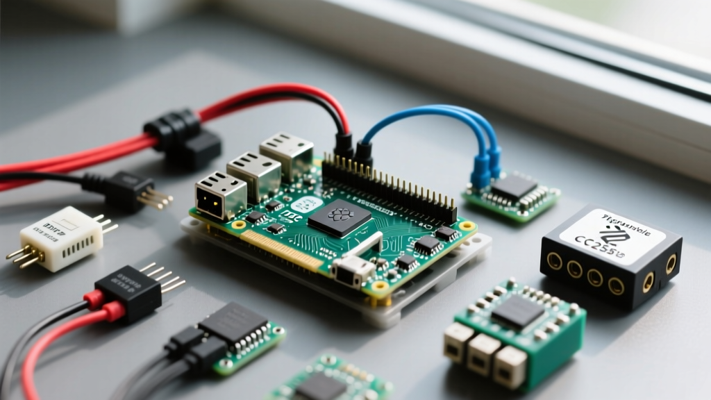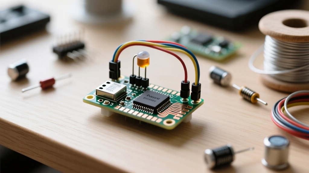

When makers and agricultural engineers search for a reliable microcontroller to build environmental monitors, the raspberry pico (officially the Raspberry Pi Pico) consistently tops the list. Priced at just $4, the RP2040-based board offers dual-core ARM Cortex-M0+ processing, 264KB of SRAM, and a highly flexible PIO (Programmable I/O) subsystem. However, building a robust, long-term soil moisture tracker requires navigating specific hardware quirks that beginner tutorials often ignore.
In this advanced project tutorial, we will design a low-power, capacitive soil moisture node. We will bypass the common pitfalls of the RP2040’s internal Analog-to-Digital Converter (ADC), address galvanic corrosion in sensor probes, and implement a hardware power-gating circuit to achieve true deep-sleep micro-amp currents for off-grid solar deployments.
Why the RP2040 Architecture Fits Sensor Nodes
The RP2040 is a powerhouse for edge computing, but its internal ADC requires careful handling. According to the official RP2040 Datasheet, the internal ADC is a 12-bit SAR (Successive Approximation Register) converter. While 12-bit resolution theoretically provides 4096 discrete steps, real-world testing reveals significant non-linearity and a DC offset error, particularly in the lower 100mV of the input range.
Overcoming ADC Non-Linearity and Noise
If your capacitive soil sensor outputs a voltage between 0V and 1.2V, you will likely encounter noisy, erratic readings due to the RP2040's ADC non-linearity near the ground rail. Furthermore, powering the Pico via USB VBUS introduces high-frequency switching noise from the onboard RT6154 buck-boost converter into the 3.3V rail, which directly impacts the ADC reference voltage.
The Engineering Fix: Instead of relying on the internal 3.3V reference, we will power the Pico via the VSYS pin using an external, low-noise LDO (Low Dropout Regulator) like the MCP1700-33. Additionally, we will use an op-amp voltage divider circuit to shift the sensor's output signal from the 0-3.3V range into the 0.8V-2.5V range, keeping the signal squarely in the ADC's most linear 'sweet spot'.
Selecting the Right Probe: Capacitive vs. Resistive
A critical failure mode in DIY irrigation projects is the use of resistive soil moisture sensors. Resistive probes pass a direct current through the soil, causing rapid electrolysis. Within two weeks, the metal traces will corrode and dissolve into the dirt.
You must use a capacitive soil moisture sensor (such as the DFRobot SEN0193 or generic v1.2/v2.0 modules). These sensors measure the dielectric permittivity of the surrounding soil by generating an oscillating frequency that varies with water content, completely isolating the electrical traces from the soil.
Warning: The generic 'v1.2' capacitive sensors have a known manufacturing flaw where the top edge ground plane is exposed. If buried directly in wet soil, this causes a short circuit. You must apply a silicone conformal coating (e.g., MG Chemicals 422C) over the entire PCB, leaving only the designated sensing pads exposed.
Hardware Bill of Materials (BOM)
| Component | Model / Specification | Est. Price | Engineering Notes |
|---|---|---|---|
| Microcontroller | Raspberry Pi Pico (RP2040) | $4.00 | Use the standard version; W (wireless) is unnecessary for local logging. |
| Soil Sensor | Capacitive v2.0 (Corrosion Resistant) | $2.50 | Ensure it uses a 555-timer or dedicated capacitance IC, not raw traces. |
| Voltage Regulator | MCP1700-3302E/TO (3.3V LDO) | $0.80 | Provides ultra-low noise for the ADC reference rail. |
| Power Timer | TI TPL5110 Nano Power Timer | $3.50 | Required to cut VSYS power for true deep sleep. |
| MOSFET | SI2301 P-Channel SOT-23 | $0.15 | Acts as the high-side switch controlled by the TPL5110. |
| Power Source | 18650 Li-Ion + Solar TP4056 | $6.00 | Provides months of autonomous runtime. |
Wiring Topology and Power Gating
To achieve battery life measured in months rather than days, we cannot rely on the RP2040's software machine.deepsleep() or dormant modes. The Pico's quiescent current in dormant mode still hovers around 1.3mA due to the onboard RT6154 and flash memory leakage. For a 2000mAh 18650 battery, 1.3mA will drain the cell in roughly 64 days, assuming zero active sensor reading time.
Instead, we implement a hardware power gate using the TPL5110 timer and a P-channel MOSFET.
Circuit Connections
- Sensor VCC: Connect to the Pico's
3V3(OUT)pin (Pin 36). - Sensor GND: Connect to Pico
GND(Pin 38). - Sensor AOUT: Connect to Pico
GP26 / ADC0(Pin 31). - VSYS Power Gate: The positive terminal of the battery/solar array connects to the Source of the SI2301 MOSFET. The Drain connects to the Pico's
VSYS(Pin 39). The TPL5110 pulls the MOSFET Gate low to turn the Pico on, and drives it high to cut power entirely. - Done Signal: Connect Pico
GP15to the TPL5110DRV/DONEpin. The Pico will pulse this pin high once the sensor reading and SD-card logging are complete, instructing the timer to cut the power.
MicroPython Implementation and Calibration Logic
For firmware, we utilize MicroPython due to its rapid iteration cycle and robust hardware abstraction layer. Refer to the MicroPython RP2 Quick Reference for detailed ADC class documentation.
import machine
import utime
import os

# Initialize ADC on GP26
adc = machine.ADC(26)

# Pin to signal the TPL5110 to cut power
done_pin = machine.Pin(15, machine.Pin.OUT)
done_pin.value(0)

def read_moisture():
    # Take 50 samples to average out high-frequency noise
    samples = []
    for _ in range(50):
        samples.append(adc.read_u16())
        utime.sleep_ms(10)

    avg_raw = sum(samples) / len(samples)

    # Convert 16-bit unsigned int to voltage (assuming 3.3V reference)
    voltage = (avg_raw / 65535) * 3.3
    return voltage

def map_voltage_to_vwc(voltage):
    # Polynomial calibration curve derived from empirical testing
    # Dry soil = ~2.8V, Saturated soil = ~1.2V
    # VWC = Volumetric Water Content (Percentage)
    if voltage >= 2.8:
        return 0.0
    elif voltage <= 1.2:
        return 100.0
    else:
        # Linear interpolation for the active range
        vwc = (2.8 - voltage) / (2.8 - 1.2) * 100
        return round(vwc, 2)

# Main Execution
v_reading = read_moisture()
moisture_pct = map_voltage_to_vwc(v_reading)

print(f'Voltage: {v_reading}V | Soil Moisture: {moisture_pct}%')

# TODO: Write moisture_pct to SD Card or transmit via LoRa

# Signal TPL5110 to cut power and enter hardware sleep
utime.sleep_ms(100)
done_pin.value(1)
Deriving the Polynomial Calibration Curve
The code above uses a simplified linear interpolation, but professional agronomy requires precise Volumetric Water Content (VWC) mapping. To calibrate your specific sensor and soil matrix:
- Air Dry Reading: Hold the sensor in dry air and record the ADC voltage (typically ~2.9V).
- Submersion Reading: Submerge the sensor in a glass of distilled water and record the voltage (typically ~1.1V).
- Soil Matrix Adjustment: Soil density and salinity alter the dielectric constant. Take a soil sample, weigh it, dry it in an oven at 105°C for 24 hours, and weigh it again to determine the exact gravimetric water content. Map your Pico's voltage readings against these empirical weights to generate a 3rd-order polynomial regression curve for your specific garden bed.
Field Deployment and Ingress Protection
When deploying your raspberry pico node outdoors, the microcontroller itself must be protected from humidity and condensation. While the capacitive probe is buried, the Pico and LDO circuitry should be housed in an IP67-rated Polycarbonate enclosure.
Use a Gore-Tex vent plug on the enclosure to allow barometric pressure equalization while blocking liquid water. Without this vent, temperature drops at night will cause the internal air to contract, creating a vacuum that pulls moisture in through the cable glands. By combining the RP2040's processing capability with a hardware-gated power supply and proper conformal coating, you create a soil moisture tracker that rivals commercial $200+ agricultural sensors for a fraction of the cost.