
The Evolution of the Raspberry Pi Remote in Smart Homes
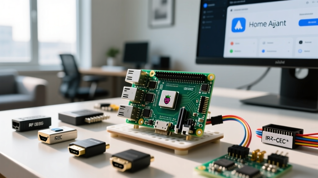
As smart home ecosystems mature, the clutter of proprietary physical remotes has become a major pain point for enthusiasts. While commercial universal hubs exist, they often rely on cloud connectivity, suffer from limited protocol support, and restrict local execution. Building a custom raspberry pi remote bridge offers a superior, privacy-focused alternative. By leveraging the GPIO header, native HDMI-CEC capabilities, and USB RF dongles, a single Raspberry Pi 4 or 5 can act as a multi-protocol command center, translating Home Assistant automations into infrared, radio frequency, and CEC signals.
This guide details the exact hardware, circuit design, and software configuration required to build a robust, multi-protocol Raspberry Pi remote bridge that integrates seamlessly with Home Assistant via MQTT.
Hardware Selection: Multi-Protocol Transceivers
A true universal remote bridge must speak the language of your legacy and modern devices. Below is a comparison of the three primary protocols you will integrate into your Pi-based hub.
| Protocol | Hardware Required | Target Devices | Range & Limitations |
|---|---|---|---|
| Infrared (IR) | TSOP38238 Receiver, 940nm IR LEDs, 2N2222 Transistor | AV Receivers, AC Units, Legacy TVs, Projectors | Line-of-sight required; ~8-10 meters max range. |
| HDMI-CEC | Native Pi HDMI Port (No extra hardware) | Modern TVs, Soundbars, Streaming Sticks | Wired via HDMI; limited to one command per 100ms. |
| RF (433MHz) | RTL-SDR USB Dongle or CC1101 SPI Module | Smart Plugs, Motorized Blinds, Weather Sensors | Omnidirectional; ~15-30 meters through walls. |
Wiring the GPIO Infrared Emitter and Receiver Circuit
The most common mistake when building a raspberry pi remote bridge is attempting to drive an IR LED directly from a GPIO pin. The Raspberry Pi GPIO pins can safely source only about 16mA. High-power 940nm IR LEDs require 100mA to 200mA to achieve room-spanning range. Therefore, a transistor switching circuit is mandatory.
The IR Transmitter (TX) Circuit
To build the emitter, you will need a 2N2222 NPN transistor, a 10kΩ resistor, a 100Ω current-limiting resistor, and your 940nm IR LEDs.
- GPIO 17 (TX): Connect to the 10kΩ resistor, then to the Base of the 2N2222.
- Emitter Pin: Connect directly to the Pi's Ground (GND).
- Collector Pin: Connect to the Cathode (short leg) of the IR LED array.
- LED Anode: Connect through the 100Ω resistor to the Pi's 5V power rail (Pin 2). Using 5V instead of 3.3V significantly increases the forward voltage headroom, allowing you to wire two IR LEDs in series for wider coverage.
The IR Receiver (RX) Circuit
For learning remote codes, the Vishay TSOP38238 is the industry standard 38kHz receiver. To prevent power supply noise from triggering false signals, the datasheet strictly recommends a filtering circuit.
- VCC: Connect to 3.3V via a 100Ω series resistor. Place a 4.7µF electrolytic capacitor directly across the VCC and GND pins of the sensor.
- OUT: Connect directly to GPIO 18 (RX).
- GND: Connect to the Pi's Ground.
Configuring Device Tree Overlays in Raspberry Pi OS
With the hardware assembled, you must instruct the Linux kernel to route the PWM and GPIO signals correctly. In the latest Raspberry Pi OS Bookworm releases, the configuration file has moved to /boot/firmware/config.txt.
Open the file and append the following dtoverlay directives:
# Enable IR Receiver on GPIO 18
dtoverlay=gpio-ir,gpio_pin=18

# Enable IR Transmitter on GPIO 17
dtoverlay=gpio-ir-tx,gpio_pin=17
After rebooting, the system will generate /dev/lirc0 (receiver) and /dev/lirc1 (transmitter). You can verify the hardware mapping by running dmesg | grep lirc in the terminal.
Expert Insight: If you are capturing IR codes using
irrecord, ensure your ambient lighting does not include CFL or inverter-based LED bulbs. These ballasts emit high-frequency noise in the 30-40kHz spectrum that will completely blind the TSOP38238 sensor, resulting in corrupted LIRC configuration files.
Bridging HDMI-CEC for AV Receiver and TV Control
Infrared is unreliable for devices hidden inside media cabinets. Fortunately, the Raspberry Pi features native HDMI-CEC (Consumer Electronics Control) support wired directly to Pin 13 of the HDMI connector. This allows your raspberry pi remote bridge to send discrete power, volume, and input commands to your TV without any external wiring.
Install the CEC utilities via the terminal:
sudo apt update
sudo apt install cec-utils libcec-dev
You can now scan the CEC bus to find your TV's logical address (usually 0 for TVs, 4 for playback devices):
echo 'scan' | cec-client -s -d 1To turn the TV off via a Home Assistant automation, you simply execute a shell command:
echo 'standby 0' | cec-client -s -d 1For audio control, CEC allows the Pi to send volume up/down commands directly to a compatible AV receiver, completely bypassing the need for IR blasters taped to your soundbar.
Integrating RF 433MHz Signals via RTL-SDR
Many smart home devices, particularly motorized blinds, outdoor temperature sensors, and cheap RF smart plugs, operate on the 433MHz ISM band. Instead of buying a dedicated hub, plug an RTL-SDR USB dongle into your Pi. Using the open-source rtl_433 daemon, your Pi can passively listen to every RF remote in your house, decode the proprietary protocols (like Princeton or PT2262), and publish the states to MQTT.
This effectively turns your Pi into a universal RF remote sniffer, allowing you to trigger Home Assistant automations based on physical button presses from legacy RF remotes.
Home Assistant Integration: The MQTT Bridge
Home Assistant natively supports MQTT integrations, making it the perfect companion for a DIY raspberry pi remote hub. Because Home Assistant has deprecated direct LIRC integrations, the most robust method is to write a lightweight Python script on the Pi using paho-mqtt and python-lirc.
The Python script subscribes to an MQTT topic like smart_home/ir/send. When Home Assistant publishes a payload (e.g., {'device': 'sony_tv', 'command': 'power_toggle'}), the script intercepts it and triggers irsend SEND_ONCE sony_tv power_toggle via the local LIRC socket.
Home Assistant YAML Configuration
In Home Assistant, you can expose this as a universal remote entity using the MQTT HVAC or generic MQTT command line integrations. For a simple TV power toggle, add this to your configuration.yaml:
shell_command:
  tv_power_toggle: >-
    mosquitto_pub -h 192.168.1.50 -t 'smart_home/ir/send'
    -m '{"device": "sony_tv", "command": "KEY_POWER"}'
This architecture ensures that your Pi handles the heavy lifting of protocol translation, while Home Assistant remains the centralized logic engine.
Troubleshooting Signal Dropout and Range Issues
When deploying a DIY IR bridge, range and reliability are the most common hurdles. Follow this diagnostic framework if your commands fail to register:
- Carrier Frequency Mismatch: While 38kHz is standard, some older Sony devices use 40kHz, and certain Bang & Olufsen equipment uses 455kHz. If
irsendfails, check your LIRC config file and adjust thefrequencyparameter to match the original remote. - Voltage Sag on the 5V Rail: Firing high-power IR LEDs draws sudden current spikes. If your Pi resets or drops WiFi packets during transmission, your power supply is inadequate. Upgrade to an official 5.1V / 3.0A USB-C power supply and add a 1000µF decoupling capacitor across the 5V and GND rails on your breadboard.
- CEC Bus Collisions: HDMI-CEC is a shared bus. If your Pi sends commands while a streaming stick is also polling the bus, packets will drop. Use
cec-clientto monitor the bus and introduce a 50ms software delay between sequential CEC commands in your Python bridge script.
Conclusion
Constructing a multi-protocol raspberry pi remote bridge is one of the most rewarding hardware projects for smart home enthusiasts. By combining GPIO-driven IR, native HDMI-CEC, and RTL-SDR RF sniffing, you eliminate the need for proprietary plastic hubs. The result is a unified, local-first control plane that integrates flawlessly with Home Assistant, ensuring your smart home remains responsive, private, and entirely under your control.
For further reading on device tree configurations, consult the official Raspberry Pi config.txt documentation, and review the LIRC project archives for advanced macro scripting.