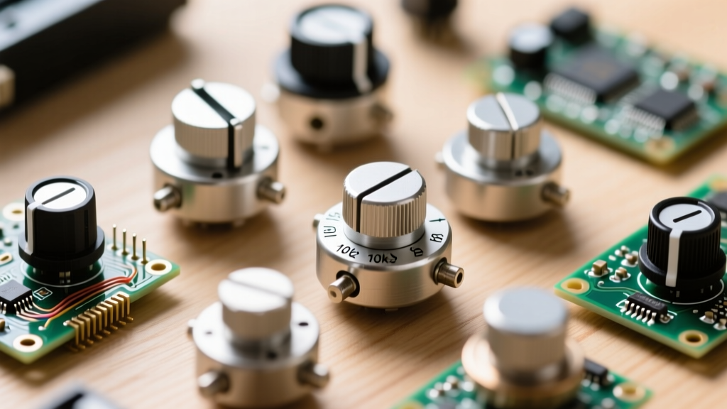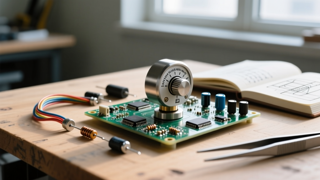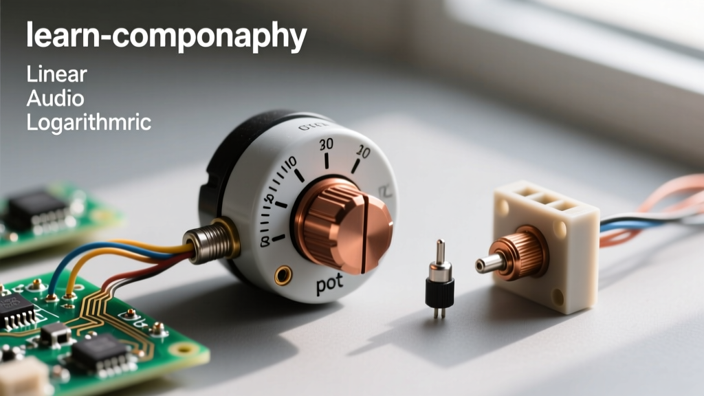

When designing analog control interfaces, audio mixing consoles, or precision calibration circuits, engineers often obsess over the electrical specifications of a potentiometer: the resistance value, the taper (linear vs. logarithmic), and the wiper contact resistance. However, the mechanical interface—specifically the potentiometer holder, mounting bracket, and bushing hardware—is frequently an afterthought. This oversight leads to catastrophic mechanical failures, wiper lift-off, and erratic signal noise. In this datasheet breakdown, we dissect the mechanical specifications of potentiometer holders and panel-mount hardware, translating obscure engineering drawings into actionable prototyping and manufacturing guidelines.
Why the Mechanical Datasheet Matters for Pot Mounts
A potentiometer is fundamentally an electromechanical transducer. The 'holder'—whether that refers to the integrated threaded bushing on a panel-mount pot or the specialized adapter brackets used to mount PCB trimmers to a front panel—bears the brunt of all physical user interaction. When a user turns a knob, they are not just applying rotational force to the shaft; they are applying lateral shear and axial thrust to the potentiometer holder.
If the holder's mechanical tolerances are misunderstood, the resulting stress transfers directly into the resistive element. For carbon composition tracks, this stress can cause microscopic fracturing. For cermet elements, it can lead to delamination. By carefully reading the mechanical outline drawings and mounting specifications on datasheets from manufacturers like Bourns and Vishay, designers can prevent these hidden failure modes before the first prototype is even assembled.
Decoding the Bushing and Thread Specifications
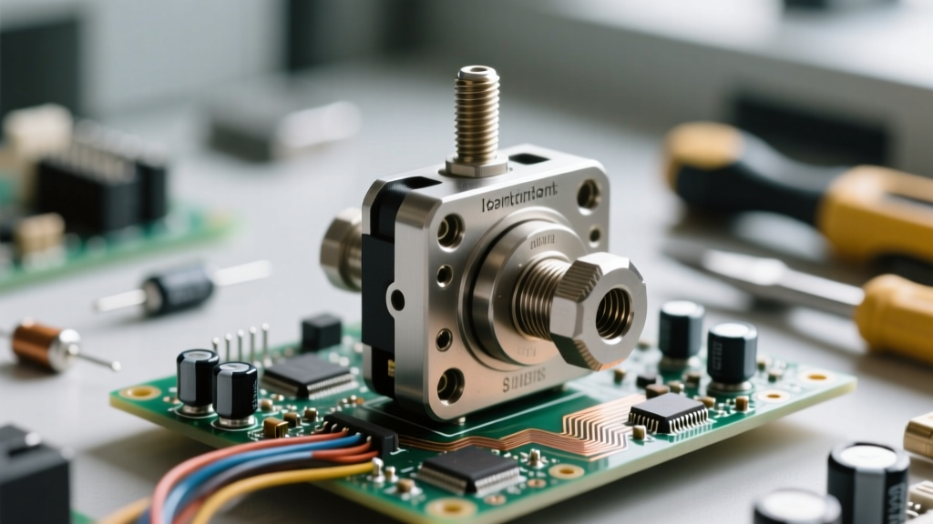
The most critical section of any panel-mount potentiometer datasheet is the bushing specification. The bushing is the cylindrical protrusion that passes through the enclosure panel, secured by a lockwasher and a mounting nut. Understanding the thread designation is vital for ensuring your enclosure's CNC-milled or punched holes match the hardware perfectly.
Standard Imperial vs. Metric Threads
In the North American market, the undisputed industry standard for 1/4-inch (6.35mm) shaft potentiometers is the 3/8"-32 UNEF-2A thread. Let us break down what this alphanumeric string actually means:
- 3/8": The nominal major diameter of the threaded bushing (0.375 inches or 9.525mm). Your panel hole must be drilled to at least 0.386" (9.8mm) to allow clearance.
- 32: The number of threads per inch (TPI). This is a 'fine' thread, chosen specifically to prevent the mounting nut from vibrating loose under high-frequency acoustic environments, such as guitar amplifiers or stage audio gear.
- UNEF: Unified National Extra Fine. This standard dictates the exact thread angle (60 degrees) and pitch.
- 2A: The tolerance class for external threads, indicating a standard clearance fit that prevents galling when mating with a steel or brass nut.
Conversely, metric designs typically utilize an M7 x 0.75 thread for similar form factors. Attempting to force a 3/8" nut onto an M7 bushing will cross-thread and destroy the brass housing, a common mistake in mixed-origin BOM (Bill of Materials) assemblies.
Panel Thickness and Torque Tolerances
Datasheets provide strict limits on panel thickness and maximum mounting torque. The panel thickness dictates the length of the bushing required. If your enclosure is too thick, the lockwasher and nut will bottom out on the unthreaded shoulder of the bushing, preventing the pot from being secured. If the panel is too thin, the anti-rotation tab (locating pin) may not engage properly, causing the entire potentiometer to spin inside the enclosure when the user turns the knob.
| Hardware Type | Thread Specification | Max Panel Thickness | Max Mounting Torque |
|---|---|---|---|
| Standard Panel Bushing | 3/8"-32 UNEF-2A | 0.375" (9.5mm) | 15 oz-in (0.11 N-m) |
| Metric Panel Bushing | M7 x 0.75 | 8.0mm | 1.2 N-m (170 oz-in) |
| PCB Trimmer Adapter Bracket | N/A (Clip-on/Screw) | 1.5mm (PCB Mount) | 5 oz-in (0.035 N-m) |
| Heavy Duty Servo Mount | 1"-20 UNEF | 0.500" (12.7mm) | 40 oz-in (0.28 N-m) |
The Hidden Danger: Over-Torquing the Mounting Nut
One of the most pervasive errors in DIY electronics and low-tier manufacturing is the over-tightening of the potentiometer mounting nut. When an assembler uses a standard 3/8" hex socket on a power drill or applies excessive manual force with a wrench, they easily exceed the 15 oz-in torque limit specified in the datasheet.
Engineering Note: Exceeding the maximum mounting torque does not just strip the threads. The axial compression forces the internal stator housing against the carbon or cermet resistive track. This physical deformation alters the wiper's tracking geometry, resulting in localized dead spots, increased contact resistance, and premature wear of the wiper fingers.
To prevent this, always use a calibrated torque screwdriver or a specialized thin-wall potentiometer nut driver that limits leverage. Furthermore, always utilize the included star lockwasher or shake-proof washer between the nut and the panel to maintain tension without requiring extreme torque.
Material Selection: Phenolic vs. Metal Brackets
When utilizing PCB trimmers (like the ubiquitous Bourns 3296 or 3386 series) in applications requiring panel access, engineers must use a potentiometer holder bracket. These adapter brackets clip onto the trimmer body and provide a threaded bushing or a shaft extension. The material of this holder is critical.
Phenolic (Bakelite) Holders: Common in low-cost audio applications. Phenolic offers excellent electrical insulation and dampens high-frequency vibrations. However, it is brittle and has a high coefficient of thermal expansion (CTE). In environments with severe temperature cycling, a phenolic holder can crack or warp, misaligning the trimmer shaft with the front panel knob.
Zinc-Plated Steel / Stainless Brackets: Used in aerospace and industrial calibration equipment. Metal brackets provide rigid support and resist mechanical creep over decades of use. The primary drawback is the potential for galvanic corrosion if the bracket contacts dissimilar metals on the PCB or chassis without proper isolation, and the risk of shorting live traces if the bracket shifts and contacts the PCB solder joints.
Real-World Failure Modes and Troubleshooting
Even with careful datasheet analysis, mechanical integration can fail. Here is a diagnostic framework for troubleshooting potentiometer holder and mounting issues in the field:
- Symptom: 'Scratchy' or Erratic Audio/Signal.
Root Cause: Often misdiagnosed as a dirty track. In reality, the mounting nut may be over-torqued, warping the internal housing and causing intermittent wiper lift-off. Fix: Loosen the mounting nut, realign the pot, and re-torque to exactly 10-12 oz-in. - Symptom: Shaft Wobble or Eccentric Rotation.
Root Cause: The panel hole was drilled oversized (e.g., using a 10mm bit for a 3/8" bushing), causing the potentiometer to hang at an angle. The lateral stress bends the brass bushing or the carbon shaft. Fix: Use a stepped drill bit for precise hole sizing and ensure the anti-rotation tab is fully seated in a matching keyway notch in the panel. - Symptom: Knob Binding Against the Panel.
Root Cause: Incorrect bushing length selected for the panel thickness, or the potentiometer holder bracket is bottoming out against the enclosure interior. Fix: Add a secondary spacer ring behind the mounting nut to push the pot further through the panel, ensuring the shaft protrudes sufficiently for the knob to clear the enclosure surface.
Final Takeaways for Prototyping
A potentiometer is only as reliable as its mechanical mounting. When reviewing component datasheets, dedicate as much time to the mechanical outline, bushing thread specifications, and torque limits as you do to the electrical schematic. Ensure your enclosure design accounts for the exact major diameter of the 3/8"-32 UNEF or M7 threads, respect the maximum panel thickness limits, and mandate the use of torque-limited assembly tools on your production line. By treating the potentiometer holder and mounting hardware as a precision mechanical system rather than a simple fastener, you will dramatically increase the lifespan and tactile quality of your electronic devices.