
The Direct Answer: What Is the Opposite of a Conductor?
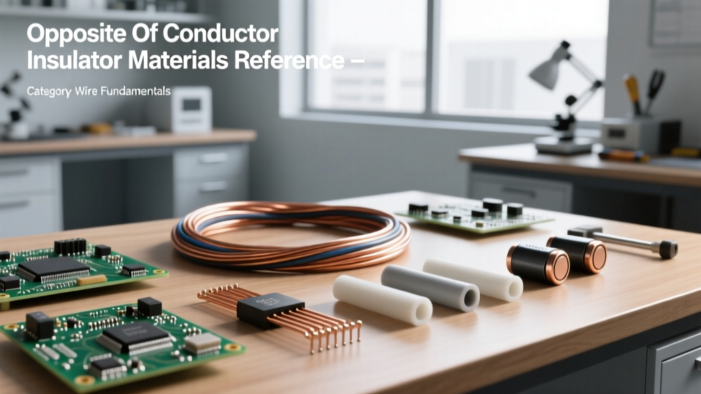
In electrical engineering and physics, the exact opposite of a conductor is an insulator. While conductors (like copper, aluminum, and silver) possess a sea of free electrons that allow electrical current to flow with minimal resistance, insulators feature tightly bound electrons that strongly resist the flow of electrical charge. According to band gap theory, conductors have overlapping valence and conduction bands, whereas insulators possess a large energy band gap (typically greater than 5 electron volts) that prevents electrons from jumping into the conduction band under normal conditions.
For electrical DIYers, wire sizing experts, and electronics engineers, understanding insulators is just as critical as understanding conductors. The insulator dictates the voltage limit, environmental resilience, and overall lifespan of a wire or cable. Without high-quality insulating materials, modern wiring systems, printed circuit boards (PCBs), and high-voltage transmission lines would be impossible to engineer safely.
Quick-Reference Data Table: Dielectric Strength of Common Insulators
When selecting wire for specific applications, you must look beyond the conductor gauge and evaluate the insulating jacket. The table below outlines the electrical and thermal limits of the most common insulating materials used in modern wiring and electronics.
| Material | Dielectric Strength (kV/mm) | Volume Resistivity (Ω·m) | Max Continuous Temp | Primary Applications |
|---|---|---|---|---|
| PTFE (Teflon) | 60 - 100 | 10^18 | 260°C | Aerospace, high-temp electronics |
| Mica | 118 | 10^15 | 500°C+ | High-voltage capacitors, heaters |
| XLPE (Cross-Linked PE) | 20 - 40 | 10^16 | 90°C | Medium/High voltage underground cables |
| PVC (Polyvinyl Chloride) | 15 - 20 | 10^14 | 70°C - 105°C | Standard residential wiring (THHN) |
| PE (Polyethylene) | 18 - 28 | 10^15 | 75°C | Coaxial cables, telecommunications |
| Air (at 1 atm) | 3 | N/A | N/A | Overhead transmission line gaps |
Application Breakdown of Top Wiring Insulators
- XLPE (Cross-Linked Polyethylene): The gold standard for medium and high-voltage underground distribution. The cross-linking process creates a 3D molecular network that prevents the polymer from melting under high fault currents, offering superior thermal stability compared to standard thermoplastics.
- PVC (Polyvinyl Chloride): The most ubiquitous insulator in residential and commercial wiring (e.g., THHN/THWN-2). It is cheap, flexible, and naturally flame-retardant due to its chlorine content. However, it degrades under prolonged UV exposure and emits toxic hydrochloric acid gas when burned.
- PTFE (Polytetrafluoroethylene): Known by the brand name Teflon, PTFE offers the lowest dielectric loss and highest thermal resistance of common wire jackets. It is heavily used in military, aerospace, and high-frequency RF applications where signal integrity at extreme temperatures is mandatory.
Insulator vs. Dielectric: Is There a Difference?
While the terms are often used interchangeably in casual DIY circles, they describe different functional properties of the same class of materials. An insulator is defined by its ability to block the flow of electrical current. A dielectric, on the other hand, is defined by its ability to store electrical energy via polarization when subjected to an electric field.
All dielectrics are insulators, but not all insulators make good dielectrics. For example, in a standard copper wire, the PVC jacket acts purely as an insulator to keep the current inside the conductor. However, in a capacitor, the material between the plates (like ceramic or tantalum oxide) acts as a dielectric, intentionally storing electrostatic energy. For a deeper dive into the atomic physics of these materials, Georgia State University's HyperPhysics provides an excellent breakdown of electron band structures.
Real-World Failure Modes: When Insulators Become Conductors
The opposite of a conductor is only effective up to its physical limits. When an insulator is pushed beyond its dielectric strength, it undergoes dielectric breakdown, suddenly becoming highly conductive and resulting in a catastrophic short circuit or arc flash. Understanding these failure modes is critical for troubleshooting electrical faults.
1. Avalanche Breakdown
When the voltage gradient across an insulator exceeds its dielectric strength (e.g., applying 30kV across a 1mm PVC gap), the intense electric field rips electrons from their atoms. These free electrons accelerate and collide with other atoms, freeing more electrons in a chain reaction known as an electron avalanche. This results in a sudden, massive spike in current that permanently carbonizes and destroys the polymer jacket.
2. Thermal Runaway and the 10-Degree Rule
Insulators degrade over time when exposed to heat. The industry relies on the Arrhenius equation, often simplified as the "10-Degree Rule": for every 10°C increase in operating temperature above the material's rated maximum, the lifespan of the insulation is cut in half. A THHN wire rated for 90°C operating continuously at 110°C will experience rapid embrittlement, leading to micro-cracking and eventual ground faults.
3. Partial Discharge and Electrical Tracking
In high-voltage cables, microscopic voids within the XLPE insulation can ionize, creating tiny, localized sparks known as partial discharges. Over years of operation, these micro-sparks erode the insulation from the inside out, creating conductive carbon pathways called "electrical trees." Once these trees bridge the gap between the conductor and the ground shield, the cable fails catastrophically.
Expert Insight: "Never assume an insulator is permanent. Environmental factors like moisture ingress, chemical exposure, and mechanical vibration drastically lower the surface resistivity of wire jackets, allowing leakage currents to track across the surface long before the internal dielectric strength is compromised."
Quick Troubleshooting: Testing Insulation Integrity in the Field
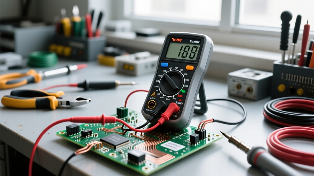
How do you verify that the opposite of a conductor is still doing its job? You cannot use a standard digital multimeter (DMM) to test insulation integrity. A standard DMM typically applies only 2 to 9 volts, which is entirely insufficient to detect microscopic weaknesses in wire jackets. Instead, professionals use a Megohmmeter (commonly referred to by the brand name Megger).
Megger Testing Basics and the Polarization Index
A Megohmmeter applies high DC voltage (typically 250V, 500V, or 1000V for low-voltage wiring) to measure the resistance of the insulation in Megohms (MΩ) or Gigohms (GΩ). According to Fluke's guide on insulation resistance testing, a healthy, newly installed residential circuit should read well above 100 MΩ. Readings dropping below 1 MΩ indicate severe moisture ingress or jacket degradation.
For large motors and heavy industrial cables, technicians use the Polarization Index (PI). This involves taking a resistance reading at 1 minute, and another at 10 minutes, then dividing the 10-minute reading by the 1-minute reading. A PI ratio of less than 1.0 indicates dangerous moisture or contamination in the insulation, while a ratio above 2.0 indicates healthy, dry insulation.
Visual and Mechanical Inspections
Beyond electrical testing, always inspect wire jackets for physical signs of failure. Look for chalking (a white, powdery residue indicating UV degradation), alligatoring (surface cracks from thermal cycling), and necking (where the jacket has stretched and thinned due to excessive pulling tension during installation). Adhering to the pulling tension limits and bend radius guidelines established by the National Electrical Manufacturers Association (NEMA) will prevent mechanical damage to the insulator before the circuit is ever energized.