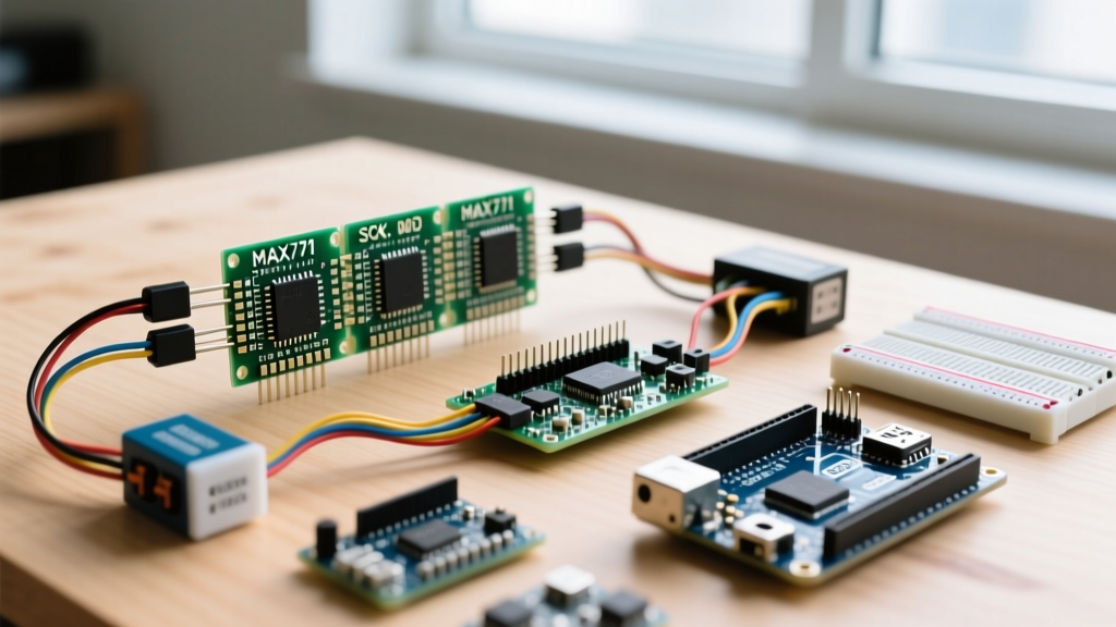

The MAX7219 module is a cornerstone of DIY electronics, offering an elegant way to drive up to 64 individual LEDs or an 8-digit 7-segment display using only three microcontroller pins. Originally designed by Maxim Integrated (now Analog Devices), this IC handles the complex multiplexing and current-limiting internally, freeing your Arduino, ESP32, or Raspberry Pi from intensive software-based PWM tasks. However, transitioning from a single module on a breadboard to a cascaded, multi-panel scrolling ticker often exposes hidden hardware quirks, power delivery bottlenecks, and logic-level mismatches. This guide provides a deep-dive engineering perspective on wiring, coding, and troubleshooting the MAX7219 module for robust DIY projects.
The Anatomy of the MAX7219 Display Module
At the heart of the standard red PCB module is the MAX7219CWG chip, paired with an 8x8 LED matrix. The IC operates by multiplexing the display at an 800 Hz refresh rate, ensuring flicker-free operation while maintaining constant current across all active segments.
A critical, often overlooked component on the module is the RSET resistor connected to pin 18. This resistor dictates the peak segment current. Most generic modules ship with a 10kΩ resistor, which limits the segment current to roughly 10mA. If you are building a high-brightness outdoor clock or a display intended for well-lit environments, you can swap this surface-mount or through-hole resistor for a 4.7kΩ value, safely pushing the current closer to 20mA per segment, provided your power supply can handle the thermal load. The formula provided in the datasheet is ISEG = (VCC - VF) / RSET * K, where K is typically 40 for standard MAX7219 implementations. By manipulating this, you can precisely tune your display's luminosity without relying solely on software PWM.
FC-113 vs. Generic Clones: Spotting the Hardware Differences
Not all MAX7219 modules are wired identically at the matrix level. The two most common variants in the DIY market are the generic 'red board' clones and the FC-113 modules.
- Generic Red Boards: The LED matrix is often soldered directly to the PCB. The internal row/column mapping usually follows a standard common-cathode layout, but cheap manufacturing runs sometimes swap the anode and cathode pins, requiring software-level rotation or mirroring.
- FC-113 Modules: These feature a distinct, separate PCB for the LED matrix that plugs into the driver board. The physical orientation of the matrix is rotated 90 degrees compared to generic clones. If you initialize an FC-113 module using generic library settings, your scrolling text will render sideways or mirrored.
Decoding the 16-Bit SPI Shift Protocol
Unlike standard I2C devices, the MAX7219 uses a proprietary SPI-like shift register protocol. It does not have a MISO (Master In Slave Out) line; it is strictly a write-only interface from the microcontroller's perspective.
Every command sent to the module is a 16-bit packet. When cascading multiple modules, the microcontroller shifts out 16 bits per module in the chain. The data passes through the DOUT pin of the first module and into the DIN pin of the second.
The 16-bit packet is structured as follows:
- Bits 15-12 (Don't Care): These bits are shifted out to the next module in the chain and are ignored by the receiving MAX7219.
- Bits 11-8 (Address): Selects the internal register. For example,
0x01to0x08addresses the individual digit/row registers, while0x0Aaddresses the Intensity register. Register0x0Cis the Shutdown register, crucial for power-saving modes, and0x0Fis the Display Test register which forces all LEDs on for factory testing. - Bits 7-0 (Data): The payload. For a row register, an 8-bit binary value dictates which LEDs in that row turn on. For the Intensity register, a hex value from
0x00to0x0Fsets the PWM duty cycle.
Understanding this packet structure is vital if you decide to bypass heavy libraries and write bare-metal SPI code for an FPGA or a highly constrained ATtiny microcontroller.
Power Delivery: The #1 Cause of MAX7219 Flickering
A frequent failure mode in DIY scrolling tickers is random flickering, resetting, or dimming when large blocks of LEDs illuminate. This is almost always a voltage drop issue. The MAX7219 can draw up to 330mA per module if all 64 LEDs are driven at maximum intensity.
Powering a 4-module cascade directly from the Arduino Uno's onboard 5V linear regulator is a recipe for thermal shutdown. The regulator will overheat, causing the voltage to sag below the MAX7219's minimum operating threshold of 4.0V, leading to erratic behavior.
| Cascaded Modules | Max Current Draw (All LEDs On) | Recommended Power Supply |
|---|---|---|
| 1 Module | ~330 mA | Arduino 5V Pin (Acceptable for testing) |
| 2 Modules | ~660 mA | Dedicated 5V 1A USB Buck Converter |
| 4 Modules | ~1.32 A | 5V 2A Switching Power Supply (e.g., Mean Well) |
| 8 Modules | ~2.64 A | 5V 3A+ PSU with parallel injection wiring |
Engineering Pro-Tip: When cascading four or more modules, the resistance of the thin PCB traces will cause a voltage drop across the chain. Inject 5V and GND directly into the VCC and GND pins of the middle modules in your chain to ensure uniform voltage distribution and prevent the first module from carrying the entire current load.
Wiring and Logic Level Translation for ESP32
Wiring the MAX7219 module to a 5V Arduino Uno is straightforward: connect VCC to 5V, GND to GND, DIN to MOSI (Pin 11), CLK to SCK (Pin 13), and CS to SS (Pin 10).
However, modern DIY projects heavily favor the ESP32 for its built-in Wi-Fi, which is perfect for fetching internet time or stock tickers. The ESP32 operates at 3.3V logic. According to the Analog Devices MAX7219 Datasheet, the minimum logic HIGH voltage (VIH) required on the DIN and CLK pins is 3.5V (when VCC is 5V).
While many hobbyists report success running 3.3V logic directly into a 5V MAX7219, this operates outside the guaranteed specifications and often results in 'ghosting' or dropped bits over long jumper wires. For a robust, commercial-grade DIY build, use a bidirectional logic level converter (like the BSS138 MOSFET-based modules) or a 74AHCT125 IC to safely shift the ESP32's 3.3V SPI signals to 5V.
Software Ecosystem: Choosing the Right Library
When coding your project, the choice of library dictates your ceiling for animation complexity.
The LedControl Library
The LedControl library is the most common entry point. It is lightweight and excellent for driving 7-segment displays or static 8x8 matrices. However, it lacks native support for complex scrolling text, sprite animations, or handling mixed hardware types (like combining FC-113 and generic modules in one chain).
The MD_MAX72XX Library
For advanced DIY projects like a retro flip-clock or a scrolling news ticker, the MD_MAX72XX library by MajicDesigns is the undisputed champion. It abstracts the hardware differences via enumerated hardware types (e.g., MD_MAX72XX::FC16_HW, MD_MAX72XX::GENERIC_HW). It also pairs seamlessly with the MD_Parola library, which handles text alignment, scrolling speeds, and font rendering, saving you hundreds of lines of bitwise shift code.
Troubleshooting Common Hardware Failures
Even with perfect code, physical layer issues can plague your MAX7219 build. Use this diagnostic framework to isolate the fault.
- Random Noise on Boot: When the ESP32 or Arduino powers on, the SPI pins may float before the
SPI.begin()function initializes them. This floating state can clock garbage data into the MAX7219. Fix: Solder a 10kΩ pull-down resistor between the CS (Chip Select) line and GND to force the module to ignore noise during boot. - High-Frequency Flickering: Long, untwisted Dupont wires act as antennas, picking up electromagnetic interference (EMI) from nearby Wi-Fi routers or switching power supplies. This noise corrupts the CLK signal. Fix: Use twisted-pair wiring for SPI, or keep wire runs under 10cm. Additionally, solder a 100nF ceramic capacitor and a 10uF electrolytic capacitor directly across the VCC and GND pins of the first and last modules to provide local decoupling.
- Inverted or Scrambled Characters: If your text is mirrored or upside down, you have likely defined the wrong hardware type in your software initialization. Check the physical board silkscreen. If it says 'FC-113', set your library parameter to
FC16_HWorFC113_HWdepending on the library's specific enum mapping.
Building with the MAX7219 module bridges the gap between simple microcontroller outputs and visually striking physical interfaces. Whether you are constructing a network-connected weather station or a retro arcade scoreboard, mastering the underlying SPI protocol and power distribution guarantees a professional, flicker-free result. For further reading on SPI bus management and clock dividers, consult the Arduino SPI Reference to ensure your hardware SPI settings are optimized for multi-module chains.