
The Fundamental Purpose of the Main Panel Bond
In electrical systems, the distinction between grounding and bonding is a frequent source of confusion, yet it is the cornerstone of life-safety in alternating current (AC) power distribution. When addressing the requirement for bonding neutral and ground at main panel NEC compliance, we are specifically talking about creating a low-impedance fault current path. Grounding refers to connecting the electrical system to the earth (via grounding electrodes like ground rods or ufer grounds), while bonding refers to connecting metallic parts of the electrical system together to ensure they are at the same electrical potential.
At the main service disconnecting means—typically the main electrical panel—the neutral conductor (grounded conductor) and the equipment grounding conductor (EGC) must be bonded together. This single point of connection is critical. If a ground fault occurs (e.g., a frayed hot wire touches a metal appliance chassis), the fault current must have a highly conductive, dedicated path back to the source (the utility transformer) to generate enough amperage to instantly trip the circuit breaker. Without the neutral-to-ground bond at the main panel, the metal chassis would simply remain energized at 120V, creating a lethal shock hazard for the next person who touches it while grounded.
Decoding NEC 250.24(A)(5) and Objectionable Current
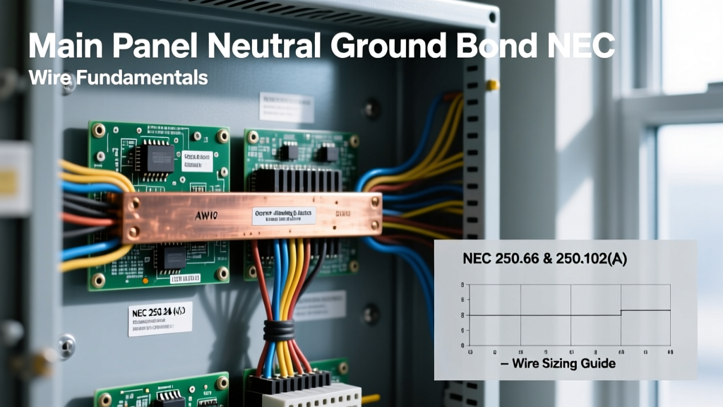
The National Electrical Code (NEC) is explicit about where this bond can and cannot occur. According to NFPA 70 (NEC) Section 250.24(A)(5), the grounded conductor (neutral) must be bonded to the service equipment enclosure via a main bonding jumper. This rule applies exclusively to the first point of disconnect on the premises wiring system.
Why restrict the bond to only the main panel? The answer lies in preventing 'objectionable current,' a concept defined in NEC 250.6. Under normal operation, the neutral conductor carries the unbalanced return current of the circuit. If you were to bond the neutral and ground at a downstream subpanel, the normal neutral return current would divide. A portion of the current would flow back to the main panel via the neutral wire, and the remainder would flow through the equipment grounding conductors, metal conduit, and even metal plumbing pipes. This parallel path creates stray voltages, electromagnetic interference, and severe shock hazards on metallic surfaces that should never carry current during normal operation.
The Physics of the Fault Current Path
Consider a 20-ampere, 120V branch circuit. If a hot-to-ground fault occurs, the impedance of the fault loop determines the fault current. The NEC requires this impedance to be low enough to facilitate the instantaneous operation of the overcurrent protective device (OCPD). By bonding the neutral and ground at the main panel, the EGC is effectively placed in parallel with the grounded service conductor back to the utility transformer's X0 terminal. This drastically reduces the total loop impedance, ensuring fault currents reach hundreds or thousands of amps, tripping the magnetic instantaneous trip mechanism of the breaker in milliseconds.
Main Service Panel vs. Subpanel: Bonding Reference Chart
One of the most common and dangerous code violations observed by electrical inspectors is the improper handling of the neutral-to-ground bond in subpanels. Use the following reference chart to verify your panel configuration against NEC requirements.
| Feature / Component | Main Service Panel (First Disconnect) | Downstream Subpanel |
|---|---|---|
| Neutral-to-Ground Bond | REQUIRED (Must be bonded) | PROHIBITED (Must be isolated) |
| Green Bonding Screw / Strap | Installed and torqued to spec | Removed and discarded or kept in bag |
| Neutral Bar Isolation | Mounted directly to panel enclosure | Floating (isolated from enclosure via plastic standoffs) |
| Ground Bar | Bonded to enclosure (often integral) | Bonded directly to enclosure |
| Grounding Electrode Conductor (GEC) | Terminates here (to ground rods/water) | Not permitted (unless separately derived system) |
| Feeder Cable Requirement | N/A (Service entrance conductors) | 4-wire (2 Hots, 1 Neutral, 1 EGC) per NEC 250.32 |
Note: If a subpanel is located in a separate building, an equipment grounding conductor must still be run with the feeder, and a separate grounding electrode system is required at the second building, but the neutral and ground bars at that second building's subpanel must still remain isolated from one another.
Sizing the Main Bonding Jumper (NEC Table 250.102(C)(1))
In large commercial services or custom-built main lug only (MLO) panels, the main bonding jumper may be a physical wire or copper strap rather than a simple green screw. The NEC mandates strict sizing for this jumper to ensure it can handle the massive available fault current from the utility transformer without vaporizing. Sizing is based on the cross-sectional area of the largest ungrounded service entrance conductor, as detailed in NEC Table 250.102(C)(1).
Copper and Aluminum Jumper Sizing Data
- Service Conductors up to 2 AWG Cu (or 1/0 Al): Requires an 8 AWG Cu (or 6 AWG Al) bonding jumper.
- Service Conductors 1/0 to 200 kcmil Cu: Requires a 6 AWG Cu (or 4 AWG Al) bonding jumper.
- Service Conductors 250 to 350 kcmil Cu: Requires a 4 AWG Cu (or 2 AWG Al) bonding jumper.
- Service Conductors 400 to 600 kcmil Cu: Requires a 2 AWG Cu (or 1/0 Al) bonding jumper.
- Service Conductors 750 to 1000 kcmil Cu: Requires a 1/0 AWG Cu (or 3/0 Al) bonding jumper.
Pro-Tip for Parallel Runs: If your service entrance conductors are run in parallel (e.g., three sets of 500 kcmil Cu per phase), you must calculate the equivalent cross-sectional area of one set of parallel conductors (3 x 500 = 1500 kcmil) to size a single main bonding jumper, or size an individual jumper for each parallel raceway based on the conductors within that specific raceway.
Hardware Specifics: Screws, Straps, and Torque Requirements
Modern residential load centers, such as the Square D HOM or QO series, and Siemens EQ series, typically utilize a green bonding screw or a specialized copper bonding strap to connect the neutral bar to the steel enclosure. When configuring a panel as a main service disconnect, this hardware must be installed.
Critically, NEC 110.14(D) requires that all electrical connections be torqu to the manufacturer's specifications using a calibrated torque tool. A typical green bonding screw requires between 45 and 50 inch-pounds of torque. Under-torquing the bonding screw introduces high resistance at the bond point, which can restrict fault current and delay breaker tripping during a short circuit. Over-torquing can strip the aluminum threads of the neutral bar, rendering the panel useless and requiring a complete replacement.
Troubleshooting Lethal Failure Modes and Code Violations
As an electrical professional or advanced DIYer, recognizing the symptoms of improper neutral-to-ground bonding is vital for system diagnostics.
- Symptom: Nuisance GFCI Tripping. If a subpanel has an illegal neutral-to-ground bond, normal return current will leak onto the equipment grounding conductor. When a GFCI device upstream or downstream detects this current imbalance (current returning via ground instead of neutral), it will trip randomly.
- Symptom: Tingling Shocks from Plumbing or Appliances. If the main panel bond is missing or has failed (e.g., a broken bonding strap), fault currents or even normal unbalanced neutral currents will seek a path to earth through the grounding electrode system. This can energize metal water pipes or appliance chassis with dangerous stray voltages.
- Symptom: Burned Neutral Bars. If a downstream subpanel is incorrectly bonded, and a neutral wire on a multi-wire branch circuit (MWBC) becomes loose or disconnected, the return current will attempt to force its way back to the main panel entirely through the equipment grounding conductors. EGCs are often sized smaller than neutrals and can overheat, melt, or cause a fire inside the walls.
Adhering strictly to the NEC guidelines for bonding neutral and ground at main panel configurations ensures that fault currents are managed predictably, keeping both the electrical infrastructure and the building's occupants safe from catastrophic electrical failures.