
The Atomic Reality: Bridging Theory and the Workbench
When students first ask, what is insulator in physics, they are usually met with a simplified definition: a material that does not conduct electricity. While true in a basic sense, this definition is practically useless for an electrical engineer, a DIY electronics hobbyist, or an electrician wiring a 240V subpanel. In the real world, there is no such thing as a 'perfect' insulator. Every material will eventually conduct if subjected to enough voltage, heat, or environmental stress.
To build safe, reliable circuits and wiring harnesses, we must look past the elementary school definition and examine the quantum mechanics and material science that govern insulating behavior. Understanding the atomic reality of insulation is the difference between a durable, high-frequency RF cable and a melted, short-circuited disaster on your soldering bench.
Band Theory and the Forbidden Gap
At the quantum level, the electrical behavior of any solid is dictated by Band Theory. Electrons in a solid occupy specific energy levels, which merge into 'bands' due to the close proximity of atoms. The two most critical bands are the valence band (where electrons are bound to atoms) and the conduction band (where electrons are free to move and carry current).
In conductors like copper, these bands overlap, allowing electrons to flow freely with minimal energy input. In semiconductors like silicon, there is a small 'bandgap' (around 1.1 eV) that can be crossed with thermal energy or doping. But what is insulator in physics terms? An insulator possesses a massive bandgap—typically greater than 5 electron volts (eV). This 'forbidden gap' means that under normal operating voltages and temperatures, electrons simply do not have the energy required to jump from the valence band to the conduction band. As noted by The Physics Hypertextbook, this vast energy barrier is what gives materials like glass, rubber, and specialized polymers their protective properties.
Dielectric Strength: The Metric That Actually Matters
While the bandgap explains why a material insulates, dielectric strength tells you when it will fail. Dielectric strength is the maximum electric field (voltage per unit thickness) that an insulating material can withstand before the atomic bonds are ripped apart, causing a catastrophic avalanche of electrons known as dielectric breakdown.
Measured in kilovolts per millimeter (kV/mm), this metric is the cornerstone of wire sizing and cable jacket selection. For instance, standard air has a dielectric strength of roughly 3 kV/mm. If you are designing a high-voltage DIY project like a Tesla coil or a neon sign transformer, you must account for the fact that electricity will arc through the air long before it breaches a solid ceramic or silicone insulator.
Real-World Insulator Material Matrix
Choosing the right wire jacket or standoff material requires balancing dielectric strength, thermal limits, and mechanical flexibility. Below is a comparison of common insulating materials used in electrical and electronics applications.
| Material | Bandgap (Approx. eV) | Dielectric Strength (kV/mm) | Max Operating Temp | Primary Real-World Application |
|---|---|---|---|---|
| PVC (Polyvinyl Chloride) | ~8.0 | 40 - 50 | 70°C - 105°C | Standard THHN/THWN building wire, low-cost jumper wires. |
| XLPE (Cross-Linked Polyethylene) | ~8.8 | 25 - 40 | 90°C - 105°C | Medium/High voltage underground utility cables, solar PV wire. |
| PTFE (Teflon) | ~10.0 | 60 - 70 | 260°C | Aerospace wiring, high-temp soldering sleeves, RF coaxial dielectrics. |
| Silicone Rubber | ~7.5 | 15 - 25 | 180°C - 200°C | 3D printer heated beds, flexible high-temp test leads, EV battery cabling. |
| Alumina Ceramic (Al2O3) | ~9.0 | 13 - 30 | 1000°C+ | Spark plug insulators, high-voltage feedthroughs, vacuum tube sockets. |
Data compiled from standard material specifications and The Engineering Toolbox.
Catastrophic Failures: When Physics Bites Back
Understanding what an insulator is in physics also requires understanding how it degrades. In the field, insulators rarely fail because the applied voltage exceeds the theoretical dielectric strength of the bulk material. Instead, they fail due to secondary physical and environmental mechanisms.
Surface Tracking and the Carbon Path
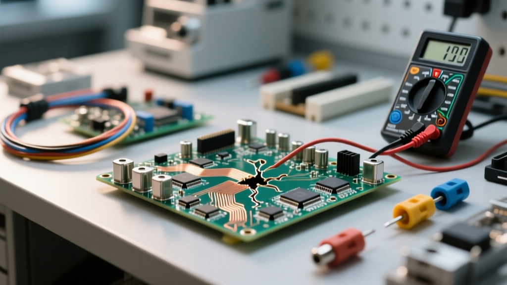
Surface tracking is an insidious failure mode, particularly in high-humidity or dusty environments. When moisture and contaminants settle on the surface of an insulator (like a PCB substrate or a high-voltage standoff), a microscopic leakage current begins to flow. Over time, this current generates localized heat, which carbonizes the surface of the polymer. Since carbon is a conductor, it creates a permanent, low-resistance path across the insulator, eventually leading to a flashover. This is why high-reliability electronics use materials with a high Comparative Tracking Index (CTI), such as specific grades of PTFE or specialized epoxies, rather than standard phenolic resins.
Thermal Breakdown at the Soldering Station
A common DIY mistake is underestimating thermal degradation. If you attempt to solder a heavy 10AWG wire to an XT60 connector using a standard PVC-jacketed wire, the heat from the soldering iron will easily exceed PVC's 105°C limit. The polymer chains break down, the jacket melts and retracts, and the exposed copper can short against the chassis. In physics terms, the thermal energy provided by the iron is exciting the electrons and degrading the physical lattice of the insulator. The practical solution is to use silicone or PTFE hook-up wire for high-current, high-heat soldering applications, as their molecular structures remain stable well past 200°C.
Applied Physics: Choosing the Right Wire Jacket
Translating the physics of insulators into a practical selection framework requires looking at the specific demands of your project.
High-Frequency and RF Applications
In high-frequency circuits, the insulator acts as the dielectric in a distributed capacitor. If the insulating material has a high dielectric constant (like PVC), it will absorb and distort high-frequency signals, leading to attenuation and phase shift. For RF applications, such as building custom antenna feeds or software-defined radio (SDR) setups, you must select insulators with a low dielectric constant and low dissipation factor. Solid PTFE or foamed polyethylene (PE) are the gold standards here, as their molecular structures do not easily polarize in response to rapidly alternating electromagnetic fields.
Expert Insight: 'Never use standard PVC wire for high-impedance analog sensor lines. The PVC jacket exhibits a piezoelectric effect and high dielectric absorption, which can inject microphonic noise and triboelectric charges into your signal path. Always route high-impedance signals through PTFE-insulated cables.' - Senior Instrumentation Engineer
High-Voltage and Corona Resistance
When operating above 2,000V, the electric field at the surface of the wire can ionize the surrounding air, creating 'corona discharge.' This plasma generates ozone and nitric acid, which rapidly eat away at standard organic insulators like PVC and rubber. If you are wiring a high-voltage power supply, an electrostatic precipitator, or a bug zapper, you must use corona-resistant insulators. XLPE and specialized silicone compounds are formulated with additives that resist ozone degradation, ensuring the physical integrity of the bandgap barrier remains intact over years of operation.
Conclusion
So, what is insulator in physics? It is a material defined by a massive valence-to-conduction bandgap, but in practice, it is a highly engineered barrier fighting against thermal, electrical, and chemical degradation. Whether you are selecting THHN wire for a residential breaker panel, choosing PTFE for an aerospace harness, or picking silicone for a 3D printer, respecting the underlying physics of dielectric strength and material limits is the ultimate key to electrical safety and reliability.