
The Atomic Divide: Why Electrons Move (Or Don't)
To truly grasp the difference between an insulator and conductor, we must look past the macroscopic world of cables, circuit boards, and soldering irons, and zoom directly into the atomic lattice. At the most fundamental level, the distinction between these two classes of materials is not about what they are made of, but rather how their subatomic particles are permitted to behave. In any solid material, electrons orbit the nucleus in specific energy levels. When atoms bond together to form a solid wire or a protective jacket, these discrete energy levels merge into continuous 'bands'.
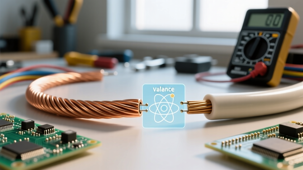
According to the principles of quantum mechanics and Georgia State University HyperPhysics, the electrical behavior of a material is dictated by the relationship between two critical bands: the Valence Band (the highest energy range where electrons are normally present at absolute zero) and the Conduction Band (the range of electron energies high enough for electrons to be free to accelerate and carry current). The gap between these two bands is known as the 'Band Gap,' and it is the ultimate gatekeeper of electrical flow.
Conductors: The Free Electron Sea
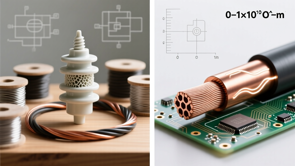
In conductive materials like copper, aluminum, and silver, the valence band and the conduction band actually overlap. There is effectively zero band gap (0 eV). This overlapping architecture means that even at room temperature, a massive 'sea' of free electrons is already residing in the conduction band. When you apply a voltage potential across a copper wire, these free electrons require virtually no additional energy to drift through the lattice, creating an electrical current. This is why copper is the undisputed king of household wiring and DIY electronics; its atomic structure practically begs electrons to move.
Insulators: The Band Gap Barrier
Conversely, the core difference when examining an insulator is the presence of a massive energy barrier. In materials like PVC (Polyvinyl Chloride), PTFE (Teflon), or XLPE (Cross-linked Polyethylene), the valence band is completely full, and the conduction band is completely empty. More importantly, the band gap separating them is enormous—typically greater than 5 to 8 electron volts (eV). At normal operating temperatures and voltages, ambient thermal energy is entirely insufficient to kick an electron across this chasm. The electrons remain tightly bound to their parent atoms, rendering the material incapable of supporting a continuous flow of charge.
Material Properties: A Data-Driven Comparison
Understanding the theoretical physics is crucial, but as an electrical DIYer or engineer, you need actionable data. The table below contrasts the physical properties of common conductors and insulators used in modern wire manufacturing and PCB design.
| Material | Classification | Resistivity (Ω·m) | Band Gap (eV) | Dielectric Strength (kV/mm) |
|---|---|---|---|---|
| Silver (Ag) | Conductor | 1.59 × 10^-8 | 0 (Overlap) | N/A |
| Copper (Cu) | Conductor | 1.68 × 10^-8 | 0 (Overlap) | N/A |
| Aluminum (Al) | Conductor | 2.65 × 10^-8 | 0 (Overlap) | N/A |
| PVC (Standard) | Insulator | ~1.0 × 10^14 | ~5.0 - 8.0 | ~40 |
| XLPE | Insulator | ~1.0 × 10^16 | ~8.0 | ~50 - 70 |
| PTFE (Teflon) | Insulator | ~1.0 × 10^18 | ~8.0+ | ~60 - 80 |
Notice the staggering logarithmic leap in resistivity. A good insulator is not just 'a little worse' at conducting than copper; it is literally trillions of times more resistant to electron flow. This immense resistivity is what allows a relatively thin layer of XLPE insulation to safely contain 600 volts inside a standard THHN wire without leaking current to the surrounding environment.
Thermal Dynamics: The Hidden Difference
One of the most critical, yet frequently overlooked, aspects of the difference between an insulator and conductor is how they react to heat. Their thermal coefficients are exact opposites, a fact that causes countless field failures when misunderstood by novice wire-sizers.
Conductors and Positive Temperature Coefficient (PTC)
As a copper or aluminum conductor heats up (due to I²R losses, or Joule heating), the atoms in the crystal lattice vibrate more violently. These vibrations scatter the free-flowing electrons, increasing the material's electrical resistance. This is known as a Positive Temperature Coefficient (PTC). In practical terms, a hot wire will experience a higher voltage drop than a cold wire carrying the exact same amperage. This is why the NFPA 70 National Electrical Code (NEC) mandates strict ampacity derating for conductors operating in high-ambient-temperature environments.
Insulators and Negative Temperature Coefficient (NTC)
Insulators behave inversely. As an insulator heats up, the ambient thermal energy begins to excite the tightly bound valence electrons. While it takes a massive amount of energy to cross a 6 eV band gap, extreme heat can push a small fraction of electrons into the conduction band. Therefore, as an insulator gets hotter, its resistance decreases. This Negative Temperature Coefficient (NTC) creates a dangerous feedback loop in failing cables: a warm insulator leaks slightly more current, which generates more heat, which lowers resistance further, eventually culminating in total thermal runaway and a short circuit.
High-Frequency Signal Routing: Skin Effect vs. Dielectric Loss
When you transition from 60Hz AC power wiring to high-frequency RF or digital signal routing (like USB-C, HDMI, or high-speed PCB traces), the difference between an insulator and conductor manifests in entirely new ways.
- The Conductor's Skin Effect: At high frequencies, alternating current refuses to travel through the center of a wire. The magnetic fields generated by the AC signal push the free electrons entirely to the outer 'skin' of the conductor. A 12 AWG solid copper wire at 10 GHz effectively acts like a hollow copper tube. This drastically increases the AC resistance compared to its DC resistance.
- The Insulator's Dielectric Loss: While DC current cannot pass through an insulator, high-frequency AC signals cause the polarized molecules within the insulator to rapidly flip back and forth to align with the changing electromagnetic field. This molecular friction generates heat and attenuates the signal. This is measured as the Dissipation Factor (Df). Standard PVC has a terrible Df, making it useless for high-speed data. PTFE (Teflon), with its highly symmetrical and non-polar molecular structure, has an exceptionally low Df, making it the premium insulator for high-frequency coaxial cables.
Real-World Failure Modes and Troubleshooting
When designing or repairing electrical systems, recognizing how these materials fail is just as important as knowing how they work. As noted by Encyclopedia Britannica, the breakdown of materials under electrical stress is a primary focus of materials science.
Insulator Failure: Tracking and Avalanche Breakdown
If you subject an insulator to a voltage beyond its dielectric strength (e.g., applying 50kV across 1mm of PVC), the electric field becomes so intense that it literally rips electrons away from their host atoms. This is called Avalanche Breakdown. The insulator momentarily becomes a conductor, resulting in a violent arc flash. Furthermore, in humid environments, insulators can suffer from 'tracking'—where surface moisture and dust create a micro-conductive path. Over time, this leakage current burns a permanent, carbonized trench into the plastic, permanently converting the surface of the insulator into a conductor.
Conductor Failure: Electromigration and Annealing
Conductors rarely fail from voltage; they fail from current and heat. If a wire is undersized for its load, the resulting heat can anneal the copper, softening it and permanently increasing its resistance. In microscopic electronics (like the traces inside a microcontroller), high current density can cause 'electromigration,' where the physical momentum of the flowing electrons literally pushes copper atoms out of place, eventually creating an open circuit void in the trace.
Summary Checklist for DIY Wiring
When selecting materials for your next project, keep these fundamental differences in mind:
- Match the Insulator to the Environment: Use XLPE for high-heat automotive environments, PTFE for high-frequency RF, and standard PVC for low-cost, indoor 60Hz AC wiring.
- Respect the Conductor's Thermal Limits: Always calculate voltage drop based on the wire's maximum operating temperature, not room temperature.
- Beware of Surface Tracking: In high-voltage DIY projects (like Tesla coils or neon sign transformers), ensure insulators are kept meticulously clean and dry to prevent surface carbonization.
Ultimately, the difference between an insulator and conductor is a masterclass in atomic architecture. By respecting the band gaps and thermal limits of the materials you work with, you ensure your circuits remain safe, efficient, and reliable for years to come.