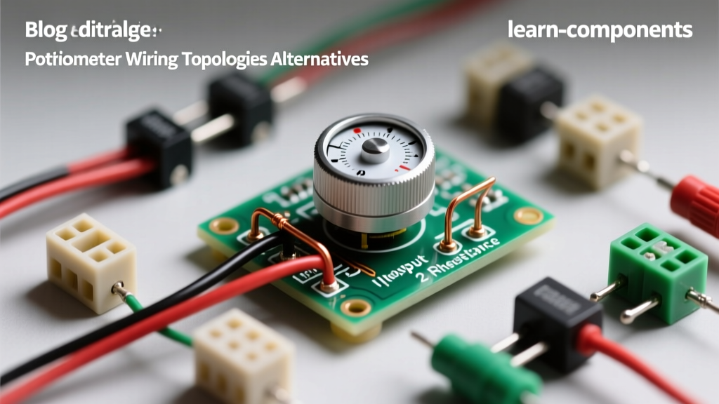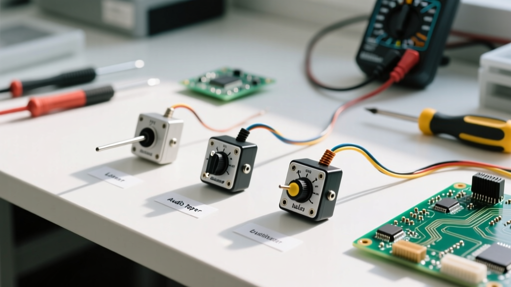

Managing an electronics lab or a production prototyping floor requires more than just buying components in bulk; it demands a strategic approach to sourcing, inventory categorization, and practical application. When junior engineers or technicians ask how to connect potentiometer circuits, the answer often depends entirely on the specific mechanical and electrical traits of the units currently sitting in your component bins. A wiring diagram is only as useful as the physical part in front of you.
From a procurement perspective, stocking the wrong taper, gang configuration, or track material can halt a prototype build or introduce catastrophic noise into an audio circuit. This guide bridges the gap between lab inventory management and bench-level wiring, ensuring your team knows exactly what to source, how to store it, and how to wire it correctly.
The Procurement Matrix: Stocking the Right Potentiometers
Before you can wire a component, you must ensure your inventory reflects the diverse needs of your engineering team. Potentiometers are not universally interchangeable. Sourcing managers should maintain a categorized stock based on track material and mechanical footprint. Below is the recommended inventory matrix for a well-rounded prototyping lab.
| Category | Model Example | Track Material | Primary Application | Sourcing Note |
|---|---|---|---|---|
| Multi-Turn Trimmer | Bourns 3296W-1-103LF | Cermet | Precision calibration, voltage reference tuning | Stock 1K, 10K, 100K. High shelf stability. |
| Single-Turn Panel | Bourns 3386P-1-502LF | Carbon / Cermet | User-facing dials, basic sensor scaling | Ensure knurled shaft compatibility with your lab's knob inventory. |
| Audio (Logarithmic) | Alps RK27 Series | Carbon Composition | Audio mixers, volume controls, faders | Strictly source 'A' taper. Prone to oxidation; store in sealed bags. |
| Digital Potentiometer | Microchip MCP41010 | Silicon / CMOS | MCU-controlled gain, automated calibration | Requires SPI/I2C. Stock in ESD-safe bins only. |
Decoding Taper: A Sourcing Pitfall
One of the most frequent inventory errors occurs when purchasing replacement potentiometers without verifying the taper code. The taper dictates how the resistance changes relative to the shaft rotation. If a technician needs to know how to connect potentiometer circuits for a volume fader, handing them a linear taper from the bin will result in a highly non-linear, frustrating user experience.
- Linear Taper (Code B): Resistance changes at a constant rate. (e.g., B10K). Essential for sensor balancing, voltage dividers, and motor speed controls.
- Audio/Logarithmic Taper (Code A): Resistance changes exponentially, matching human hearing perception. (e.g., A10K). Mandatory for audio amplification circuits.
Procurement Warning: Taper codes can be regionally inverted on vintage or surplus parts. While modern suppliers like Digi-Key standardize 'B' as Linear and 'A' as Audio, older European stock might label Linear as 'A'. Always verify surplus inventory with a multimeter before logging it into your lab's ERP system.
Bench Reference: How to Connect Potentiometer Terminals
Once the correct component is pulled from inventory, the physical wiring begins. A standard single-gang rotary potentiometer features three terminals. When viewing the shaft from the top with the terminals pointing downward, the pins are typically arranged as follows:
- Pin 1 (CCW): Counter-Clockwise terminal. Connected to the low-side or Ground.
- Pin 2 (Wiper): The variable output terminal. Physically rides along the resistive track.
- Pin 3 (CW): Clockwise terminal. Connected to the high-side or VCC.
Configuration 1: The Voltage Divider (Three-Terminal Wiring)
The most common application in microcontroller prototyping is using the potentiometer as a voltage divider to feed an analog-to-digital converter (ADC). To wire this correctly, you utilize all three pins. For a deep dive into the math behind this, refer to the SparkFun Voltage Divider Tutorial.
Wiring Steps:
- Connect Pin 1 to System Ground (0V).
- Connect Pin 3 to your Reference Voltage (e.g., 3.3V or 5V).
- Connect Pin 2 (Wiper) to the microcontroller's ADC input pin.
As the shaft rotates, the wiper sweeps across the resistive element, outputting a variable voltage between 0V and VCC. This is the standard method for reading user inputs on an Arduino or Raspberry Pi Pico.
Configuration 2: The Rheostat (Two-Terminal Fail-Safe Wiring)
When you need a variable resistor to limit current (e.g., dimming an LED or tuning an RC oscillator frequency), you only technically need two pins: Pin 1 and Pin 2. However, experienced lab managers enforce a strict "fail-safe" wiring protocol for rheostat configurations to prevent catastrophic circuit failure.
The Fail-Safe Wiper Tie:
Instead of leaving Pin 3 floating, you must jumper Pin 2 (Wiper) directly to Pin 3.
Why do this? Potentiometers are mechanical devices subject to vibration, dust, and track wear. If the wiper (Pin 2) momentarily lifts off the resistive track, a two-wire circuit becomes an open circuit (infinite resistance). In an op-amp feedback loop or a motor controller, an open circuit can cause voltage spikes, runaway feedback, or destroyed components. By tying Pin 2 to Pin 3, if the wiper drops out, the circuit defaults to the maximum resistance of the pot (e.g., 10KΩ) rather than an infinite open, safely limiting current until the component can be replaced.
Identifying Unmarked Surplus Inventory
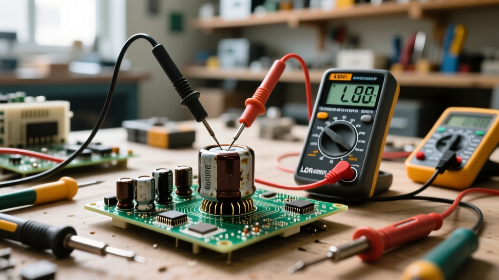
Prototyping labs frequently acquire surplus kits or unmarked bins. If you are handed a potentiometer with faded silkscreen and need to know how to connect potentiometer pins correctly, use a digital multimeter (DMM) to map the footprint.
- Set your DMM to resistance mode (Ω).
- Place probes on the two outer pins (Pin 1 and Pin 3). The reading should match the rated resistance (e.g., 10,000Ω for a 10K pot). These are your fixed track ends.
- Keep one probe on an outer pin, and move the second probe to the center pin (Pin 2).
- Rotate the shaft. If the resistance sweeps smoothly from 0Ω to the max rating, you have correctly identified the wiper and the low-side pin.
Managing Inventory Degradation and Shelf Life
Sourcing is only half the battle; maintaining the integrity of your inventory is equally critical. Unlike ceramic capacitors or resistors, potentiometers contain moving mechanical parts and exposed chemical tracks that degrade over time.
Carbon Track Oxidation
Carbon composition potentiometers (commonly used in audio applications) are highly susceptible to moisture and oxidation. If stored in non-climate-controlled environments, the carbon track develops a micro-layer of oxidation. When a technician connects this degraded part, they will experience "wiper bounce" or scratching noises in the audio output. Inventory Rule: Always store carbon-track pots in sealed, desiccant-lined ESD bags.
Cermet and Contact Resistance
Cermet (ceramic-metal) trimmers, like the Bourns 3296 series, offer incredible stability and are detailed extensively in Bourns Trimmer Design Considerations. However, their multi-turn wipers can accumulate microscopic debris if left exposed on a dusty workbench. Never pull a cermet trimmer from inventory and solder it directly to a PCB without first cycling the adjustment screw 10-20 times. This "wiping" action clears the contact point of any shelf-dust or minor oxidation, ensuring a stable contact resistance (CRV) before it goes into the reflow oven.
Summary for Lab Managers
Understanding how to connect potentiometer circuits is inextricably linked to how you source and store them. By maintaining a diverse inventory of linear and audio tapers, enforcing fail-safe rheostat wiring practices, and protecting mechanical components from environmental degradation, your lab will eliminate a massive category of prototyping errors. Treat your electromechanical components with the same rigorous inventory controls as your sensitive silicon ICs, and your bench technicians will have the reliable parts they need to build flawless circuits.