
"My first robotic arm shook so violently it unscrewed its own base. The secret wasn't better code; it was realizing that 5V USB power banks lie about their peak current output." — Alex T., ElectricalFlux Forum Member
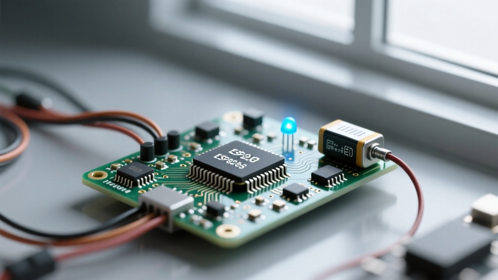
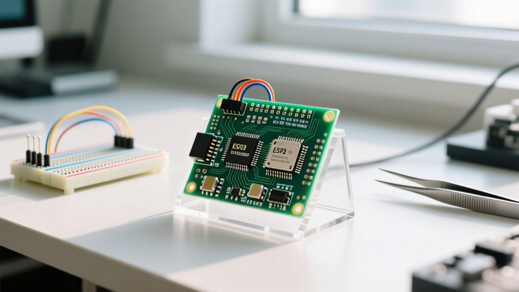
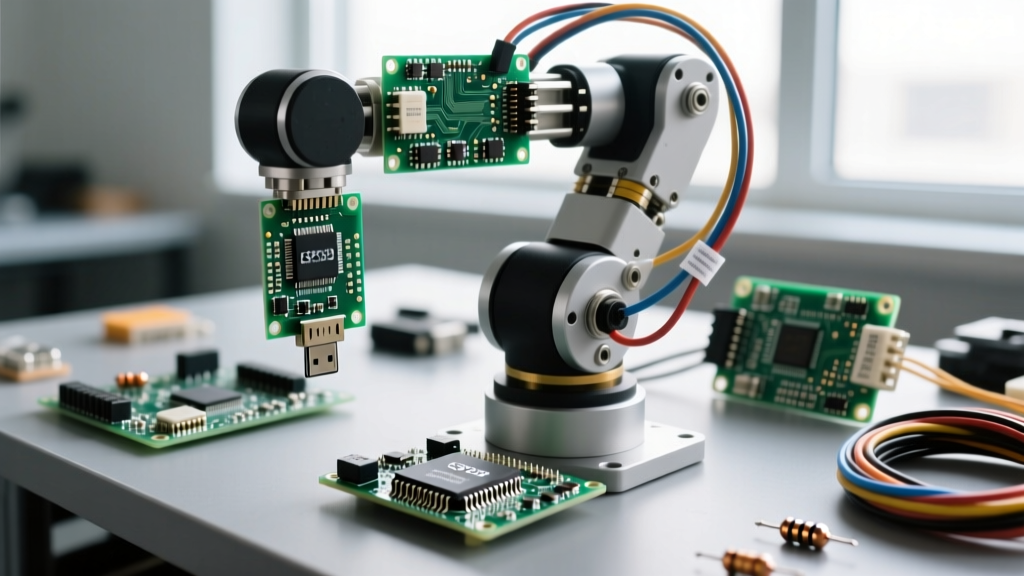
Welcome back to the ElectricalFlux Community Showcase. This month, we are dissecting a spectacular 6-Degree-of-Freedom (6-DOF) robotic arm built by community member Alex. While the internet is flooded with basic 4-DOF acrylic kits, Alex’s build bridges the gap between toy-grade kits and industrial manipulators. By leveraging an ESP32 microcontroller, a dedicated I2C PWM driver, and high-torque metal-gear servos, this project serves as a masterclass in mechatronics.
The Core Question: How to Construct a Robotic Arm That Actually Works
When makers first ask how to construct a robotic arm, they are usually directed toward cheap, potentiometer-based kits. While great for learning basic kinematics, these kits fail in real-world applications due to severe PWM jitter, insufficient payload capacity, and structural flex. Alex’s approach discards the toy-grade paradigm. Instead of driving servos directly from the microcontroller's GPIO pins—which introduces timing interrupts and jitter whenever the Wi-Fi radio fires up—this build offloads PWM generation to a dedicated coprocessor.
The result is a smooth, repeatable manipulator capable of lifting a 450g payload with sub-millimeter precision at the end effector. Below, we break down the exact architecture, power mathematics, and software stack required to replicate this community benchmark.
Bill of Materials: Upgrading from Acrylic to Aluminum
Structural rigidity is paramount. Alex replaced the standard laser-cut acrylic chassis with 2mm CNC-machined aluminum brackets. This prevents the "spring effect" that causes oscillation when the arm extends to its maximum reach.
| Component | Model / Specification | Est. Price | Why We Chose It |
|---|---|---|---|
| Microcontroller | ESP32-WROOM-32 DevKit | $6.50 | Dual-core processing allows one core to handle Wi-Fi/UDP streaming while the other calculates kinematics. |
| Servo Driver | PCA9685 16-Channel PWM | $4.00 | Hardware I2C PWM generation eliminates ESP32 timer conflicts and Wi-Fi jitter. |
| Base/Shoulder Servos | DSSERVO DS3218 (20kg-cm) | $22.00 x2 | Massive stall torque required to hold the arm against gravity when fully extended. |
| Elbow/Wrist Servos | TowerPro MG996R (13kg-cm) | $9.00 x3 | Metal gears provide durability for mid-arm articulation without excessive weight. |
| Gripper Servo | TowerPro MG90S (Micro) | $5.00 | Low profile and lightweight to minimize inertia at the end effector. |
| Power Supply | Mean Well LRS-100-5 (5V 20A) | $28.00 | Provides clean, continuous 100W to handle simultaneous servo stall currents. |
| Chassis | Custom 2mm Aluminum Brackets | $45.00 | Eliminates chassis flex and harmonic oscillation during rapid movements. |
Power Delivery: The Silent Killer of DIY Servo Arms
The most common reason community builds fail—or worse, catch fire—is inadequate power delivery sizing. To understand how to construct a robotic arm that survives its first hour of operation, you must calculate the worst-case current envelope.
Calculating the Current Envelope
A standard MG996R servo draws roughly 500mA under normal operation but can spike to 2.5 Amps at stall. If your arm loses balance and all six servos hit a mechanical hard stop or stall simultaneously, the instantaneous current draw can exceed 12 Amps.
- The Mistake: Powering the arm via a 5V 3A USB-C buck converter. The voltage sags to 3.8V, the ESP32 brownouts, and the servos behave erratically.
- The Fix: Alex utilized a Mean Well LRS-100-5 enclosed switching power supply, rated for 5V at 20A (100W).
Furthermore, Alex soldered a 4700µF electrolytic capacitor directly across the main 5V and GND terminal blocks on the PCA9685 board. This acts as a local energy reservoir, absorbing the microsecond current spikes when multiple servos change direction simultaneously, protecting the I2C logic from voltage droop.
I2C Wiring and the PCA9685 Servo Driver
Driving high-torque servos directly from the ESP32 GPIO pins is a recipe for disaster. The ESP32's software PWM is constantly interrupted by the RTOS and Wi-Fi stack, resulting in a visible 50Hz jitter that destroys servo potentiometers over time.
The PCA9685 solves this by accepting simple I2C commands and generating the precise 50Hz PWM signals via its own internal hardware clock.
Wiring Specifics and Pull-Up Resistors
Alex connected the ESP32's default I2C pins (GPIO 21 for SDA, GPIO 22 for SCL) to the PCA9685. However, a critical community discovery was the necessity of 4.7kΩ pull-up resistors on both the SDA and SCL lines. While many cheap PCA9685 breakout boards include these, they are often tied to the board's 5V logic. Because the ESP32 operates on 3.3V logic, Alex removed the onboard 5V pull-ups and added external 4.7kΩ resistors tied to the ESP32's 3.3V pin to prevent long-term degradation of the ESP32's I2C transceivers.
Inverse Kinematics: Moving Beyond Record-and-Playback
Most beginner tutorials teach forward kinematics or simple "record-and-playback" macros. But to truly understand how to construct a robotic arm for automation, you must implement Inverse Kinematics (IK). IK allows you to define a target XYZ coordinate in 3D space, and the math calculates the exact joint angles required to place the end effector at that point.
Implementing the FABRIK Algorithm
Alex opted for the FABRIK (Forward And Backward Reaching Inverse Kinematics) algorithm over traditional Denavit-Hartenberg (DH) parameter matrices. FABRIK is computationally lightweight, making it perfect for the ESP32's dual-core architecture.
- Core 0 handles the UDP network stack, receiving XYZ target coordinates from a Python-based GUI on a host PC.
- Core 1 runs the FABRIK solver at 100Hz, translating XYZ vectors into six distinct PWM pulse widths (ranging from 500µs to 2500µs).
By utilizing the Adafruit PCA9685 library as a foundation, Alex modified the I2C transmission buffer to send all six servo updates in a single I2C burst transaction, eliminating the micro-stutters caused by sequential I2C writes.
Real-World Failure Modes and Community Fixes
No build is perfect on the first iteration. Here are the specific failure modes Alex encountered and how the ElectricalFlux community helped resolve them:
- Failure Mode 1: I2C Bus Lockups. During rapid movements, electrical noise from the servo motors coupled into the I2C data lines, causing the ESP32 to freeze. Solution: Rerouting the I2C cables away from the servo power lines and adding a 100nF decoupling capacitor across the V+ and GND of every individual servo.
- Failure Mode 2: Shoulder Gear Stripping. The MG996R servos originally used in the shoulder joint stripped their internal aluminum gears under the static load of the extended arm. Solution: Upgrading the base and shoulder joints to the DSSERVO DS3218 (20kg-cm) with hardened steel gears, and implementing software-based "soft limits" to prevent the arm from holding heavy loads at maximum horizontal extension.
- Failure Mode 3: End-Effector Oscillation. The gripper vibrated when closing on hard objects. Solution: Adding a physical compliance layer (3D printed TPU rubber pads) to the gripper jaws, combined with a software current-sensing routine that reduces PWM duty cycle once a stall threshold is detected.
Community Takeaways
Alex’s 6-DOF build proves that bridging the gap between hobbyist and prosumer robotics isn't about spending thousands on harmonic drives; it's about respecting the physics of power delivery and offloading timing-critical tasks to dedicated hardware. If you are planning your own manipulator, start by sizing your power supply for worst-case stall conditions, isolate your logic from your motor noise, and embrace inverse kinematics early in your software development. Have a build you want featured? Drop your schematics and BOMs in the ElectricalFlux Projects forum for a chance to be in next month's Showcase.