
Why Standard Wire Charts Fail in the Real World
If you have ever glanced at a generic chart for electrical wire size on the back of a wire spool, you might think sizing a circuit is as simple as matching the breaker amperage to a single number. In the controlled environment of a textbook, that works. In the real world of residential and commercial wiring, a basic chart is only the starting line.
Real-world electrical installations are governed by the National Electrical Code (NEC / NFPA 70), which requires electricians to factor in ambient temperature, conductor bundling, termination limits, and voltage drop. Ignoring these variables doesn't just result in a failed inspection; it leads to melted insulation, tripped breakers, and catastrophic fire hazards. This guide bridges the gap between the theoretical ampacity chart and the messy, hot, and complex realities of the job site.
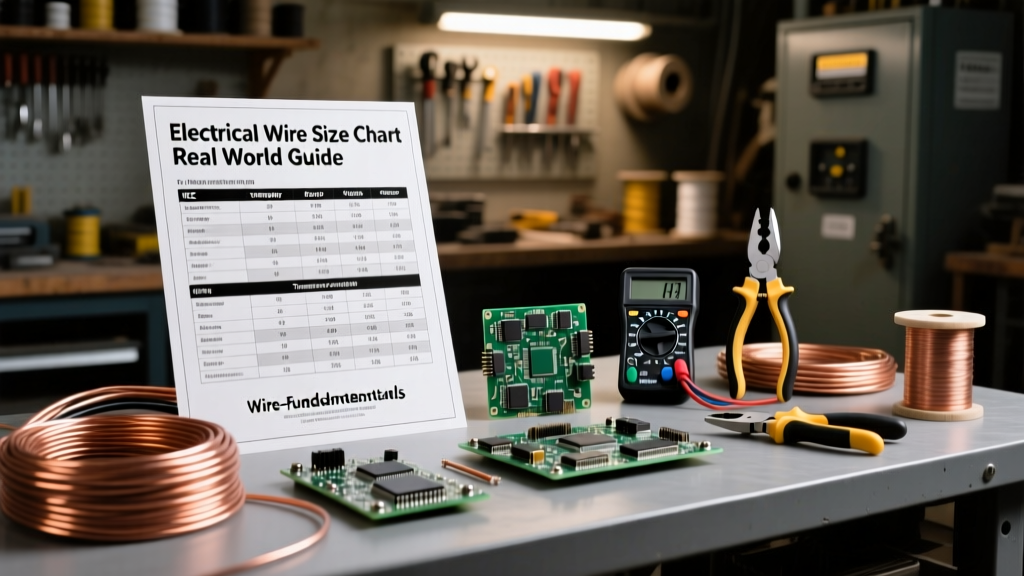
The Core Chart for Electrical Wire Size (NEC Table 310.16 Breakdown)
Below is a streamlined, real-world adaptation of NEC Table 310.16 for copper conductors. Notice the three distinct temperature columns. Understanding the difference between these columns is the single most important skill in wire sizing.
| AWG / kcmil | 60°C (TW, UF) | 75°C (THHW, USE) | 90°C (THHN, XHHW) | Typical Real-World Application |
|---|---|---|---|---|
| 14 | 15A | -- | -- | Lighting circuits, 15A receptacles (NEC 240.4(D) limits) |
| 12 | 20A | 25A | 30A | Kitchen small appliance, bathroom, 20A general circuits |
| 10 | 30A | 35A | 40A | Dryers, water heaters, 30A RV receptacles |
| 8 | 40A | 50A | 55A | Large appliance feeds, 50A EV chargers (with derating) |
| 6 | 55A | 65A | 75A | 60A subpanels, tankless electric water heaters |
| 4 | 70A | 85A | 95A | 100A subpanel feeders (short runs) |
| 3 | 85A | 100A | 110A | 100A main service entrance, long 100A subpanel runs |
| 2 | 95A | 115A | 130A | 125A service upgrades, heavy commercial feeders |
The 90°C Trap: Why Terminations Dictate Your Sizing
Amateur DIYers and first-year apprentices frequently make a dangerous mistake: they buy THHN wire (rated for 90°C), look at the 90°C column on the chart, and assume they can push 40 Amps through a 10 AWG wire on a 40A breaker. This is a direct violation of NEC 110.14(C).
The Weakest Link Rule: The ampacity of a circuit is limited by the lowest temperature rating of any connected component. Most standard breakers, lugs, and receptacles are rated for 75°C or 60°C.
Even if your wire is rated for 90°C, if it terminates on a standard 75°C breaker lug, you must use the 75°C column to determine your maximum overcurrent protection. So, a 10 AWG THHN wire is still limited to 35A for termination purposes, meaning it cannot be placed on a 40A breaker.
When is the 90°C Column Actually Useful?
The 90°C column is not useless; it is your secret weapon for derating. You use the 90°C ampacity as your baseline before applying ambient temperature and bundling correction factors. Once the math is done, you verify that the final derated number does not exceed the 75°C or 60°C termination limits.
Real-World Variable 1: Ambient Temperature Derating
Wire charts assume an ambient temperature of 30°C (86°F). If you are pulling wire through an unconditioned attic in Arizona during July, the ambient temperature can easily exceed 50°C (122°F). Heat prevents the wire from dissipating its own resistive heat, leading to insulation breakdown.
Calculating the Correction Factor
Let us look at a real-world scenario: You are running a 30A circuit to a rooftop HVAC unit. The conduit is strapped to the roof, exposed to the sun, with an expected ambient temperature of 115°F (46°C). You plan to use 10 AWG THHN.
- Base Ampacity (90°C column): 40A
- Temperature Correction Factor (46-50°C): 0.82 (per NEC Table 310.15(B)(1))
- Derated Ampacity: 40A × 0.82 = 32.8A
Because 32.8A is greater than our 30A breaker, and 32.8A does not exceed the 75°C termination limit of 35A, this installation is safe and code-compliant. If you had blindly used the base chart without derating, the wire would slowly cook inside the conduit.
Real-World Variable 2: Conductor Bundling (The 'More Than Three' Rule)
When you pull multiple current-carrying conductors through a single raceway or conduit, they heat each other up. The NEC requires you to reduce the allowable ampacity (bundle derating) when you have more than three current-carrying conductors. Note that grounding conductors and grounded neutrals that only carry unbalanced current do not count toward this total.
Standard Bundling Derating Percentages
- 4 to 6 conductors: 80% of base ampacity
- 7 to 9 conductors: 70% of base ampacity
- 10 to 20 conductors: 50% of base ampacity
Field Scenario: You are pulling two 20A multi-wire branch circuits (MWBC) through a single EMT conduit. That is 4 current-carrying conductors (two hots, two neutrals). You want to use 12 AWG THHN.
- Base 90°C Ampacity: 30A
- Bundling Factor (4 wires): 0.80
- Derated Ampacity: 30A × 0.80 = 24A
Since 24A is greater than the 20A breaker, and 24A is below the 60°C/75°C termination limits, 12 AWG THHN is perfectly legal here. However, if you added a third circuit (6 wires, 80% factor), you would still be at 24A. But if you added a fourth circuit (8 wires, 70% factor), your derated ampacity drops to 21A. While technically above 20A, you are now operating with virtually zero safety margin, and many local inspectors will require you to upsize to 10 AWG or split the runs into separate conduits.
The Hidden Killer: Voltage Drop Over Distance
The NEC ampacity charts dictate how much current a wire can handle before it catches fire. They do not guarantee that the equipment at the end of the wire will receive adequate voltage. The NEC recommends (via Informational Notes) a maximum voltage drop of 3% for branch circuits and 5% total for feeder and branch circuits combined. For deep dives on this, the Southwire Voltage Drop Calculator is an invaluable field tool.
Sizing Up for Long Runs
Imagine you are wiring a detached garage 150 feet away from the main panel. You need a 120V, 20A circuit to run a table saw (which draws 15A under load).
- Using 12 AWG Copper: The voltage drop is roughly 5.4%. The saw will receive only 113V. The motor will overheat, draw excess amperage, and eventually burn out.
- Using 10 AWG Copper: The voltage drop drops to roughly 3.4%. Still slightly high for a heavy motor starting surge.
- Using 8 AWG Copper: The voltage drop is 2.1%. The saw receives 117.5V, ensuring optimal torque and motor longevity.
In this real-world application, you must install 8 AWG wire and terminate it on pigtails (since 8 AWG solid wire often will not fit into standard 20A receptacle screw terminals). The chart for electrical wire size told you 12 AWG was fine for 20A, but physics demanded 8 AWG.
Field Troubleshooting: When the Chart Gets You in Trouble
Even seasoned professionals occasionally run into issues when they misinterpret the chart. Here are two common failure modes encountered in the field:
- The Aluminum/Copper Confusion: Many older homes and modern service entrance cables (like SER) use aluminum. Aluminum has a higher resistance than copper. If you look at the copper column for a 100A subpanel and pull 4 AWG, but accidentally buy 4 AWG aluminum, your ampacity drops to 55A. The wire will overheat. Always verify the material column on your chart.
- The Continuous Load Trap: NEC 210.20(A) requires that if a load is expected to run for 3 hours or more (like a commercial lighting array or a continuous-duty HVAC blower), the overcurrent device and wire must be sized at 125% of the continuous load. A 20A continuous load requires a wire and breaker sized for 25A. A basic chart will not remind you of this multiplier.
Summary Checklist for the Job Site
Before you cut your first length of wire, run your project through this professional decision framework:
- Step 1: Determine the total load and apply the 125% continuous load multiplier if applicable.
- Step 2: Select the base wire size using the appropriate chart for electrical wire size (matching the termination temperature rating, usually 75°C).
- Step 3: Apply ambient temperature correction factors if the wire is in an attic, crawlspace, or on a roof.
- Step 4: Apply bundling derating factors if pulling more than 3 current-carrying conductors in a raceway.
- Step 5: Calculate voltage drop. If the run exceeds 100 feet, upsize the conductors by at least one or two AWG sizes to maintain equipment efficiency.
- Step 6: Verify that the final chosen wire size is compatible with the physical lugs on your breakers and terminals.
Mastering wire sizing is about moving beyond the basic chart and understanding the thermal and electrical environment your conductors will live in. For further study on complex derating scenarios, resources like Mike Holt Enterprises offer exceptional NEC code breakdowns that translate dense legal text into practical job-site rules.