
The Engineering Dilemma: Why E96 Resistor Values Matter
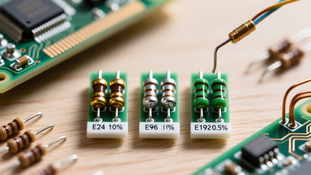
In modern PCB design and prototyping, selecting the right resistor series is a critical decision that impacts both circuit performance and manufacturing scalability. The IEC 60063 standard defines the E series of preferred numbers, but for precision analog work, E96 resistor values have become the undisputed workhorse. Offering 96 logarithmic steps per decade, the E96 series is intrinsically linked to 1% tolerance components. But when should you pivot to the cheaper E24 (5%) or the ultra-precise E192 (0.1%) alternatives? This guide compares these series to help you optimize your Bill of Materials (BOM) without sacrificing signal integrity.
Decoding the EIA Decades: E24 vs. E96 vs. E192 Alternatives
The core difference between the E-series lies in their step size and the resulting tolerance overlap. The formula for any E-series value is the Nth root of 10, where N is the series number.
Tolerance Overlap and the 1% Sweet Spot
The E96 series features a step size of approximately 2.42% ($10^{1/96} \approx 1.0242$). Because the step size is greater than the 2% total tolerance band (±1%), there are no gaps in the available resistance values. This makes E96 the mathematical minimum required for a guaranteed 1% tolerance selection. According to DigiKey's Guide to Resistor Tolerances, using an E24 component (which has a ~10% step size) with a 1% tolerance creates massive gaps, forcing designers to use series/parallel combinations to hit specific targets.
Inventory and BOM Cost Implications
While E96 provides precision, it demands more unique part numbers on your PCB. If your design requires 15 different resistor values, and all fall on E96 steps, you will need 15 separate feeders on a Pick-and-Place (PnP) machine. Conversely, standardizing on E24 values allows you to use 5% thick-film resistors, which are exponentially cheaper and often available in multi-decade kits. For high-volume consumer electronics, designers often round E96 calculated values to the nearest E24 equivalent to save on reel setup costs, provided the circuit can tolerate the 5% deviation.
Comparative Data: Standard E96 Base Values per Decade
To visualize the density of the E96 series compared to the E24 alternative, consider the first few steps of the 10-ohm decade.
| Step Index | E24 Value (5%) | E96 Value (1%) | Differential Gap |
|---|---|---|---|
| 1 | 10.0 | 10.0 | Base |
| 2 | 11.0 | 10.2 | 0.2 Ω |
| 3 | 12.0 | 10.5 | 0.3 Ω |
| 4 | 13.0 | 10.7 | 0.2 Ω |
| 5 | 15.0 | 11.0 | Matches E24 Step 2 |
As shown, the E96 series fills the voids left by E24, allowing precision tuning for voltage dividers and feedback networks without resorting to trimming potentiometers.
Real-World Prototyping Scenarios: When to Pivot from E96
Choosing between E-series alternatives is rarely just about the initial resistance value; it is about the secondary characteristics like Temperature Coefficient of Resistance (TCR) and parasitic capacitance. Analog Devices emphasizes that the physical construction of the resistor often matters more than the nominal E-series value in precision circuits.
Scenario A: High-Gain Transimpedance Amplifiers (TIA)
In a TIA used for photodiode signal conditioning, the feedback resistor dictates both the gain and the noise floor. If your calculation demands a 133kΩ feedback resistor, you will find that 133k is a standard E96 value (Code: 13). However, a standard 1% thick-film E96 resistor might have a TCR of ±100 ppm/°C and high parasitic capacitance. In this scenario, the alternative is not a different E-series, but a different technology. You must pivot to a 0.1% thin-film E96 resistor (like the Susumu RG or Vishay TNPW series) with a ±25 ppm/°C TCR to prevent thermal drift from ruining your signal-to-noise ratio.
Thick-film resistors also exhibit significant voltage coefficient of resistance (VCR) at high bias voltages, meaning the actual resistance drops as the voltage across the component increases. Thin-film E96 alternatives maintain linearity even across 50V potential differences, making them non-negotiable for high-voltage photomultiplier tube (PMT) biasing networks.
Scenario B: Pull-up Networks and LED Current Limiting
If you are designing an I2C bus pull-up network or an LED indicator circuit, targeting E96 values is a waste of BOM budget. An I2C pull-up resistor simply needs to meet the rise-time requirements dictated by the bus capacitance. Whether you use 4.7kΩ (E24) or 4.75kΩ (E96) is electrically irrelevant. Sticking to the E24 5% alternative reduces your unique part count and leverages the cheapest, most ubiquitous components on the market.
SMD Marking Codes: The Hidden Language of E96
When prototyping with 0402 or 0603 SMD components, identifying E96 resistor values on the bench can be frustrating. Unlike E24 resistors that use a standard 3-digit or 4-digit numerical code, 1% E96 SMD resistors frequently use the EIA-96 marking system. This system uses two digits followed by a letter.
- The Digits (01-96): Represent the significant figures based on a lookup table (e.g., 01 = 100, 02 = 102, 03 = 105... 13 = 133).
- The Letter (Multiplier): Represents the power of 10. For example, 'A' = $10^0$, 'B' = $10^1$, 'C' = $10^2$, 'D' = $10^3$.
Therefore, an SMD resistor marked 01C translates to significant figure 100 multiplied by $10^2$, yielding exactly 10.0kΩ. An SMD marked 13D translates to 133 multiplied by $10^3$, yielding 133kΩ. Keeping an EIA-96 cheat sheet on your lab bench is mandatory for rapid DIY troubleshooting.
It is important to note that some manufacturers are beginning to abandon the EIA-96 code on 0402 packages simply because the packages are too small to laser-mark reliably, opting instead to leave the top surface blank and rely entirely on smart feeders and reel scanning during automated assembly. For manual DIY prototyping, always use a precision multimeter to verify blank 0402 components before soldering.
Pro-Tip for PnP Feeder Optimization: If your lab's Pick-and-Place machine only has 20 feeder slots, but your BOM requires 25 unique E96 values, look for values that can be safely swapped. For instance, replacing a 10.2kΩ (E96) with a 10kΩ (E24/E96 overlap) in a non-critical biasing network can free up a vital feeder slot without compromising the prototype's functionality.
Synthesizing Non-Standard Values When E96 Falls Short
Even with 96 values per decade, you will occasionally calculate a required resistance that falls between E96 steps—such as 11.4kΩ. Before switching to a costly multi-turn trimpot, consider synthesizing the value using standard E96 alternatives in series or parallel.
Using two 1% resistors in series or parallel actually improves the statistical distribution of your tolerance. If you place two 22kΩ E96 resistors in parallel, you get 11kΩ, but the random manufacturing variance of the two resistors will partially cancel each other out, yielding an effective tolerance closer to 0.7%. For the 11.4kΩ target, placing a 12kΩ and a 180kΩ E96 resistor in parallel yields exactly 11.25kΩ, which is often well within the acceptable error margin for analog sensor biasing.
Furthermore, when designing for high-frequency RF applications, placing resistors in series can help distribute parasitic parallel capacitance, effectively pushing the self-resonant frequency (SRF) of the combined component higher into the GHz range. This is a common trick when designing 50-ohm termination networks using standard E96 SMD chip resistors.
Final Verdict: Standardizing Your Lab Inventory
Ultimately, E96 resistor values represent the optimal intersection of precision and availability for modern electronics. While E24 remains the king of digital logic pull-ups and basic current limiting, and E192 is reserved for metrology-grade instrumentation, the 1% E96 series is the mandatory baseline for op-amp feedback loops, precision voltage references, and RF matching networks. By understanding when to strictly enforce E96 values and when to relax your BOM to E24 alternatives, you can drastically reduce prototyping costs while maintaining rigorous analog performance.