
The Anatomy of the 28BYJ-48: Beyond the Datasheet
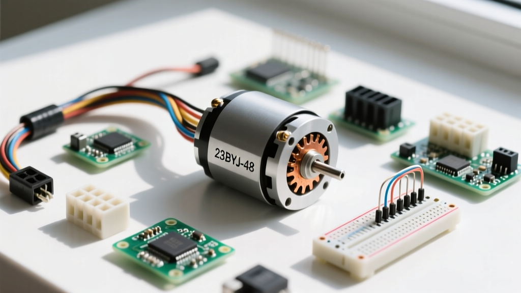
If you have ever built an Arduino-based pan-and-tilt camera mount, a mini CNC plotter, or an automated pet feeder, you have likely encountered the 28BYJ-48 stepper motor. Retailing for under two dollars, this 5V unipolar, 4-phase motor is the undisputed gateway to DIY motion control. However, relying on the cheap, mass-produced datasheets included with these motors is a common trap for beginners. To truly master this component and achieve precise positional accuracy, we must look past the marketing specs and examine its real-world electromechanical behavior.
According to the standard Components101 28BYJ-48 datasheet, the motor features a stride angle of 5.625°/64 and a 1:64 gear reduction ratio. In theory, this yields exactly 4096 steps per revolution. In practice, however, your DIY projects will slowly drift out of alignment if you program your microcontroller using that exact number.
The Infamous 63.68 Gear Ratio Explained
The most critical piece of information gain for advanced DIYers is the reality of the internal gear train. The motor does not actually possess a 1:64 gear ratio. The physical teeth counts on the internal brass and plastic spur gears (specifically the 9-tooth and 11-tooth pinions interacting with the 22-tooth and 32-tooth drive gears) result in an exact mathematical reduction ratio of 63.683950617:1.
What does this mean for your Arduino code? It means one full rotation requires exactly 4075.77 steps (often rounded to 4076) when using a half-stepping sequence, rather than the 4096 steps claimed by the documentation. If you are building a continuous rotation mechanism like a radar sweep or a camera slider, failing to account for this 0.5% discrepancy will result in noticeable positional drift over hundreds of cycles.
Hardware Integration: Wiring the ULN2003 Driver Board
The 28BYJ-48 cannot be driven directly from microcontroller GPIO pins. It requires roughly 240mA per phase, which would instantly fry an ATmega328P. Instead, it is almost universally paired with a ULN2003 Darlington transistor array board.
While the ULN2003 is incredibly cheap and easy to use, it suffers from a fundamental electrical characteristic that DIYers often overlook: voltage drop. Because the ULN2003 uses Darlington pairs to switch the current, there is an inherent voltage drop of approximately 1.0V to 1.5V across the transistors. If you supply the driver board with 5V, the motor coils are only actually receiving about 3.5V to 4.0V. This is why the 28BYJ-48 often feels surprisingly weak and lacks holding torque in 5V setups.
Pinout and Power Delivery Warnings
Pro-Tip: Never power the 28BYJ-48 directly from the Arduino's onboard 5V regulator. The motor can draw upwards of 240mA per phase, and the combined load of the motor and the Arduino logic will cause severe voltage sag, leading to brownouts and random microcontroller resets. Always use a dedicated buck converter or a USB breakout board capable of delivering at least 1.5A to the ULN2003 VCC pin.
Step Sequencing: Full Step vs. Half Step
To achieve smooth motion and minimize resonance, DIYers should almost exclusively use the half-step sequence. Half-stepping alternates between energizing one coil and two coils, effectively doubling the resolution of the motor and providing a more consistent torque curve.
| Step | Coil A (IN1) | Coil B (IN2) | Coil C (IN3) | Coil D (IN4) | Active Phases |
|---|---|---|---|---|---|
| 1 | 1 | 0 | 0 | 0 | A |
| 2 | 1 | 1 | 0 | 0 | A, B |
| 3 | 0 | 1 | 0 | 0 | B |
| 4 | 0 | 1 | 1 | 0 | B, C |
| 5 | 0 | 0 | 1 | 0 | C |
| 6 | 0 | 0 | 1 | 1 | C, D |
| 7 | 0 | 0 | 0 | 1 | D |
| 8 | 1 | 0 | 0 | 1 | D, A |
Arduino Implementation: AccelStepper Library Best Practices
While you can write a manual loop to cycle through the array above, professional DIY projects rely on the AccelStepper Library to handle acceleration, deceleration, and non-blocking motor control. However, mapping the pins correctly is a frequent stumbling block.
When initializing the AccelStepper object for a 28BYJ-48 on a ULN2003 board, you must use the HALF4WIRE constant. Furthermore, the pin order in the constructor does not match the physical 1-2-3-4 silkscreen on the driver board. You must interleave the pins to match the physical coil layout (A, B, A', B').
Assuming IN1 is on Pin 8, IN2 on Pin 9, IN3 on Pin 10, and IN4 on Pin 11, your initialization code must look like this:
AccelStepper stepper(AccelStepper::HALF4WIRE, 8, 10, 9, 11);
Notice the sequence: 8, 10, 9, 11. If you use 8, 9, 10, 11, the motor will violently stutter, vibrate, and fail to rotate because the magnetic fields are being energized out of phase.
Advanced Hack: Converting Unipolar to Bipolar
The 28BYJ-48 ships as a unipolar motor, utilizing center-tapped coils. This limits your torque and prevents the use of modern microstepping drivers like the A4988 or DRV8825. According to the RepRap Stepper Wiring Wiki, you can convert this motor to a bipolar configuration by opening the blue plastic rear housing and carefully cutting the copper trace that connects the red center-tap wire to the common ground.
This simple modification isolates the center taps, allowing you to wire the motor as a standard 4-wire bipolar stepper. By pairing the modified 28BYJ-48 with an A4988 driver at 12V, you can push the full coil current through the entire winding length. This increases holding torque by roughly 40%, eliminates the ULN2003 voltage drop issue, and enables 1/16th microstepping for ultra-quiet, glass-smooth motion in camera slider applications.
Troubleshooting Common 28BYJ-48 Failures
Jitter, Stalling, and Overheating
If your motor gets too hot to touch after a few minutes of holding position, it is likely stuck in a full-step holding state. Unipolar motors in full-step mode constantly route maximum current through half of the coil windings. To mitigate this, always command the motor to move to a position and then cut power to the ULN2003 (via a relay or MOSFET) if holding torque is not strictly required, or switch to a half-stepping routine which distributes the thermal load more evenly.
Mechanical Backlash and Gear Stripping
From a mechanical standpoint, the 28BYJ-48 is not a precision instrument. The internal gear train utilizes a mix of brass and soft plastic spur gears. The inherent backlash (slop) in the output shaft is typically between 0.5° and 1.0°. If your DIY project requires reversing direction with high precision, you must implement a software backlash compensation routine that always approaches the target coordinate from the same direction. Additionally, never subject the output shaft to heavy radial loads; the plastic output gear will strip or snap if lateral pressure exceeds a few hundred grams. Use a flexible coupler and support bearings for any lead-screw applications.