
The Fundamental Duality of Electrical Circuits
Every functional electrical system, from a simple 5V microcontroller breadboard to a 500kV cross-country transmission line, relies on a strict boundary between where electricity should flow and where it absolutely must not. When students and DIYers first ask, "what's a conductor and insulator," the answer extends far beyond simple definitions of metal and plastic. It requires an understanding of quantum mechanics, material science, and thermal dynamics. In this guide, we will dissect the atomic physics that govern electrical flow, compare real-world wiring materials, and explore the catastrophic failure modes that occur when the boundary between these two material classes breaks down.
The Atomic Divide: Valence Electrons and Band Theory
To truly understand conductivity, we must look at the outermost electron shell of an atom, known as the valence shell. The behavior of these valence electrons dictates whether a material will readily pass an electrical current or resist it entirely.
Conductors: The Sea of Free Electrons
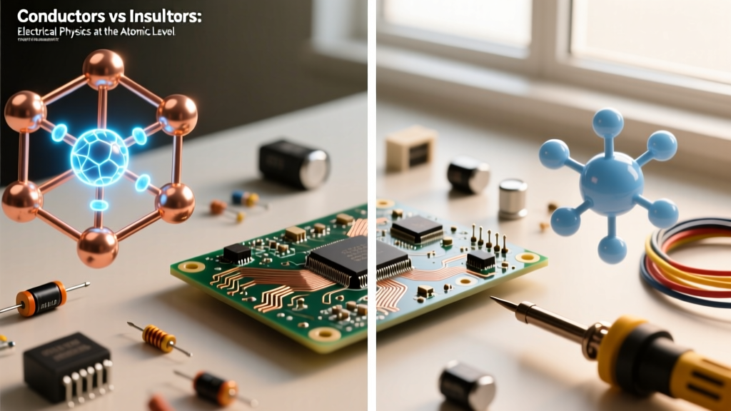
Conductive materials, primarily metals, possess one to three valence electrons. These electrons are loosely bound to their parent nuclei. According to Band Theory in solid-state physics, the valence band and the conduction band in metals overlap. This means that even at room temperature, a massive "sea" of free electrons is available to drift through the atomic lattice when an electromotive force (voltage) is applied. Copper, silver, and gold are prime examples, offering minimal atomic resistance to electron flow.
Insulators: The Wide Bandgap
Insulators, such as glass, rubber, and most polymers, have five to eight valence electrons that are tightly bound in covalent or ionic bonds. In band theory terms, insulators feature a massive "bandgap" between the valence band and the conduction band. Under normal voltage conditions, electrons simply do not possess enough energy to jump this gap. As noted in the All About Circuits textbook on conductors, it requires extreme electrical pressure (voltage) or severe thermal energy to force electrons across this gap, a phenomenon known as dielectric breakdown.
Conductors in Practice: Beyond Basic Copper
While copper is the undisputed king of residential and commercial wiring, electrical engineers must balance conductivity, weight, cost, and mechanical strength. Conductivity is typically measured against the International Annealed Copper Standard (IACS), where pure annealed copper is set at 100% IACS.
- Silver (105% IACS): The most conductive elemental metal, but prohibitively expensive for bulk wiring. It is reserved for high-end audio contacts, RF switching, and specialized aerospace busbars.
- Copper (100% IACS): The standard for NEC (NFPA 70) compliant branch circuit wiring. It offers excellent tensile strength and resists galvanic corrosion when properly terminated.
- Gold (70% IACS): A poor bulk conductor, but highly prized for micro-electronics and connector plating because it does not oxidize. A gold-plated contact ensures long-term low-resistance mating.
- Aluminum (61% IACS): Significantly lighter and cheaper than copper. While it requires a larger gauge to carry the same ampacity, modern AA-8000 series aluminum alloy is standard for heavy feeder cables and utility service drops.
The 1970s Aluminum Wiring Crisis: In the 1970s, pure aluminum was used for residential 15A and 20A branch circuits. Pure aluminum suffered from "cold creep" (expanding and contracting under heat, loosening terminal screws) and rapid surface oxidation. Aluminum oxide is an insulator, which caused high-resistance connections, arcing, and widespread house fires. Modern AA-8000 alloy and CO/ALR rated terminals solved these mechanical and chemical flaws.
Insulators and Dielectric Strength: The Unsung Heroes
An insulator's primary job is to confine the electric field to the conductor. In electrical wiring, we categorize insulators not just by their material, but by their dielectric strength (the maximum electric field they can withstand before breaking down, measured in kV/mm) and their thermal rating.
Common Wire Insulation Polymers
The National Electrical Code (NEC) classifies wire insulation by letters that denote thermal and environmental limits. For example, THHN (Thermoplastic High Heat-resistant Nylon-coated) and XHHW (Cross-Linked Polyethylene High Heat Water-resistant) are industry standards.
- PVC (Polyvinyl Chloride): The most common thermoplastic insulator. It is flexible, cheap, and flame-retardant due to its chlorine content. However, it becomes brittle in extreme cold and emits toxic hydrochloric acid gas when burned.
- XLPE (Cross-Linked Polyethylene): Through a chemical or irradiation process, the polymer chains are cross-linked into a 3D matrix. This drastically improves thermal stability, moisture resistance, and dielectric strength, making it ideal for wet locations and underground direct-burial cables.
- PTFE (Teflon): Used in aerospace, military, and high-temperature industrial applications. PTFE can withstand continuous temperatures up to 250°C and possesses an incredibly low coefficient of friction and high dielectric strength.
Comparative Data: Material Properties Matrix
The following table contrasts the physical and electrical properties of standard conductive and insulative materials used in modern electrical engineering.
| Material Class | Material Name | Resistivity (nΩ·m) / Dielectric Strength | Max Continuous Temp | Primary Application |
|---|---|---|---|---|
| Conductor | Silver | 15.87 nΩ·m | N/A | RF Contacts, Precision Shunts |
| Conductor | Copper (Annealed) | 16.78 nΩ·m | N/A | Branch Wiring, Motor Windings |
| Conductor | Aluminum (AA-8000) | ~28.00 nΩ·m | N/A | Service Feeders, Transmission Lines |
| Insulator | PVC (THHN) | ~40 kV/mm | 90°C (Dry) | Residential/Commercial Romex & THHN |
| Insulator | XLPE (XHHW) | ~50 kV/mm | 90°C (Wet/Dry) | Underground Feeders, Industrial |
| Insulator | PTFE (Teflon) | ~60 kV/mm | 250°C | Aerospace, High-Temp Sensors |
Real-World Failure Modes: When the Boundary Collapses
Understanding what's a conductor and insulator theoretically is vastly different from managing them in the field. Insulation failure is the leading cause of electrical fires, short circuits, and equipment destruction. Here is how these materials fail in real-world scenarios:
1. Thermal Degradation and the Arrhenius Equation
Insulation is highly susceptible to heat. The Arrhenius equation dictates that for every 10°C a polymer operates above its rated temperature, its chemical lifespan is halved. A 90°C rated THHN wire operating continuously at 110°C in a hot attic will experience premature plasticizer loss. The PVC becomes brittle, cracks when bent, and exposes the bare conductor, leading to ground faults.
2. Dielectric Breakdown and Corona Discharge
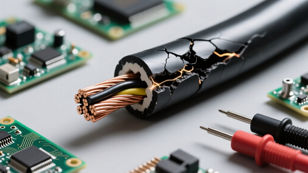
If the voltage gradient across an insulator exceeds its dielectric strength (kV/mm), the atomic bonds are literally torn apart, creating a conductive plasma channel. In high-voltage systems, this often starts as corona discharge—a localized ionization of the air surrounding the insulation. Over time, the ozone and nitric acid generated by corona discharge chemically eat away at the polymer jacket until a complete flashover occurs.
3. Conductor Oxidation at Terminations
As mentioned, aluminum oxide is an insulator. If an aluminum feeder wire is not properly treated with an antioxidant compound (like Noalox) and torqued to the manufacturer's specifications, the insulating oxide layer builds up at the lug. This increases contact resistance, generating immense localized heat (I²R losses), which can melt the surrounding insulation and ignite the panelboard.
Troubleshooting Insulation Integrity: The Megger Test
Electricians and maintenance engineers do not rely on visual inspection alone to verify insulator health. They use a Megohmmeter (commonly called a "Megger") to perform Insulation Resistance (IR) testing. By injecting a high DC voltage (e.g., 500V or 1000V) into the conductor and measuring the micro-ampere leakage current through the insulation to the ground, technicians can quantify the dielectric health. A healthy 600V rated cable should yield an IR reading in the hundreds or thousands of Megohms. A reading below 1 Megohm indicates moisture ingress, thermal cracking, or imminent dielectric failure.
Summary
The interplay between conductors and insulators forms the absolute foundation of electrical safety and functionality. Conductors provide the low-resistance pathway for energy transfer, leveraging their atomic sea of free electrons. Insulators act as the vital containment vessel, utilizing wide bandgaps and high dielectric strength to prevent catastrophic energy release. By selecting the correct IACS-rated metals and thermally appropriate polymer jackets, and by rigorously testing for insulation degradation, electrical professionals ensure that power reaches its destination safely and efficiently.