
The Atomic Divide: Band Gap Theory Explained
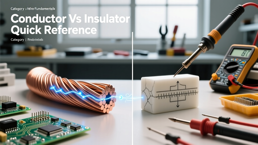
When troubleshooting a circuit or selecting materials for a custom PCB, understanding what is the difference between a conductor and insulator is the foundational step. At the macro level, conductors allow electrical current to flow freely, while insulators block it. However, at the quantum level, this behavior is dictated by band gap theory.
In solid-state physics, electrons occupy specific energy levels. The highest energy range where electrons are normally present at absolute zero is called the valence band. The range of energies that electrons can jump to in order to move freely through the material is the conduction band. According to Georgia State University's HyperPhysics, the defining difference lies in the gap between these two bands:
- Conductors: The valence and conduction bands overlap. Electrons require virtually zero additional energy to break free from their parent atoms and drift as an electrical current.
- Insulators: There is a massive energy gap (typically greater than 5 electron volts, or eV) between the bands. Electrons are tightly bound to their atoms and cannot jump to the conduction band under normal voltage conditions.
- Semiconductors: These sit in the middle, with a small band gap (around 1 eV) that can be bridged using heat, light, or chemical doping.
Quick Reference: Conductor vs. Insulator Comparison Chart
The following table provides a quick-reference breakdown of standard materials used in electrical engineering and DIY wiring, highlighting their specific resistivity and dielectric properties. Data sourced from the Engineering Toolbox.
| Material | Category | Resistivity (Ω·m at 20°C) | Dielectric Strength (kV/mm) | Max Operating Temp (°C) | Common Application |
|---|---|---|---|---|---|
| Silver (Ag) | Conductor | 1.59 × 10⁻⁸ | N/A | 961 (Melting) | High-end audio contacts, RF switches |
| Copper (Cu) | Conductor | 1.68 × 10⁻⁸ | N/A | 1085 (Melting) | Standard branch wiring, PCB traces |
| Aluminum (Al) | Conductor | 2.82 × 10⁻⁸ | N/A | 660 (Melting) | Overhead transmission, heavy feeder |
| PVC | Insulator | ~10¹⁵ | 40 - 50 | 75 - 105 | THHN wire insulation, cable jackets |
| XLPE | Insulator | ~10¹⁶ | 27 - 30 | 90 - 105 | XHHW-2 wire, high-voltage cables |
| PTFE (Teflon) | Insulator | ~10¹⁸ | 60 - 70 | 260 | Aerospace wiring, soldering iron tips |
| Mica | Insulator | ~10¹³ | 100 - 150 | 600+ | High-temp heating elements, capacitors |
| Air (Dry) | Insulator | ~10¹⁶ | ~3 | N/A | Overhead line spacing, switch gaps |
Real-World Wiring: Standard Conductors
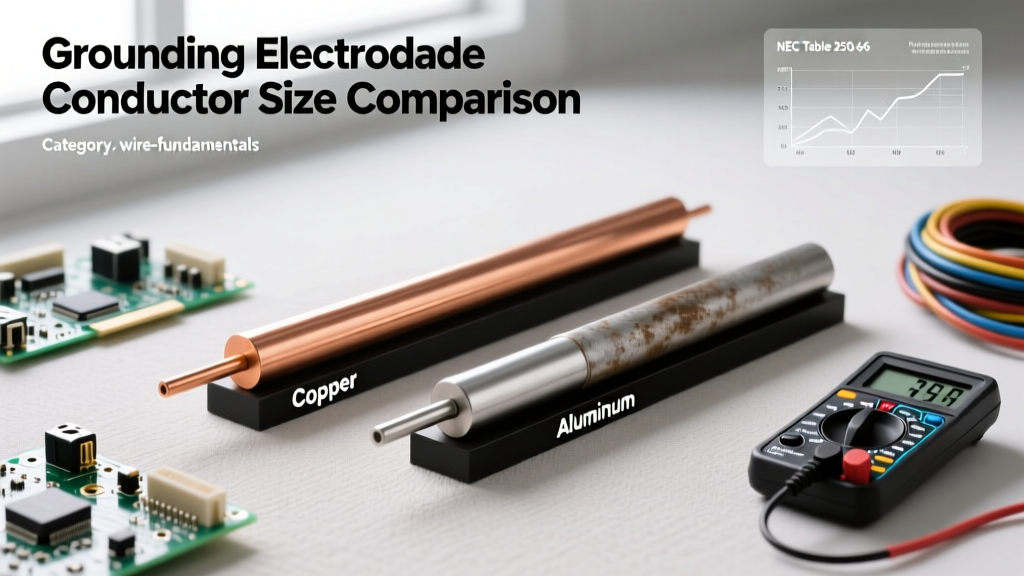
Copper vs. Aluminum in the NEC
While silver is technically the most conductive elemental metal, its cost prohibits widespread use. Therefore, the electrical industry relies on copper and aluminum. Copper is the gold standard for residential and commercial branch circuits due to its low resistivity (1.68 × 10⁻⁸ Ω·m), high tensile strength, and resistance to galvanic corrosion.
Aluminum, while possessing only about 61% of the conductivity of copper by volume, is significantly lighter and cheaper. It is heavily utilized in utility transmission lines and large residential service entrance conductors (e.g., 4/0 AWG SER cable). When working with aluminum, DIYers and electricians must use specific anti-oxidant compounds (like Noalox) and torque lugs to exact manufacturer specifications to prevent thermal expansion loops that cause high-resistance faults.
Real-World Wiring: Insulation Chemistries
Understanding what is the difference between a conductor and insulator is incomplete without examining how insulators are applied in modern wiring. The National Electrical Code (NFPA 70) classifies wires not just by their metal core, but by their insulating chemistry.
- THHN (Thermoplastic High Heat-resistant Nylon): The insulation is PVC, which provides excellent dielectric strength (~40 kV/mm). The outer jacket is Nylon, which is also an insulator but is primarily used for its extreme mechanical abrasion resistance, allowing the wire to be pulled through tight PVC conduits without tearing.
- XHHW-2 (Cross-Linked Polyethylene): XLPE is a thermoset plastic. Unlike PVC, which melts when exposed to extreme heat, XLPE retains its physical shape and insulating properties even in high-temperature or wet environments. It is the preferred insulator for underground direct-burial feeds and high-amperage subpanels.
- PTFE (Teflon): Used in specialized applications like aerospace, military, and high-end electronics. PTFE is virtually impervious to chemicals, has an incredibly high melting point (allowing it to be placed directly next to solder joints without shrinking), and boasts a massive dielectric strength of over 60 kV/mm.
Dielectric Breakdown: When Insulators Fail
An insulator is only an insulator up to a specific threshold. Dielectric breakdown occurs when the applied electric field (voltage gradient) becomes so intense that it literally tears electrons away from their host atoms, creating a conductive plasma channel.
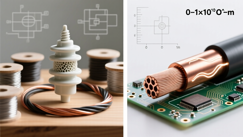
For example, dry air is an excellent insulator at low voltages. However, its dielectric strength is only about 3 kV/mm. If you apply 30,000 volts across a 10mm gap, the air undergoes avalanche breakdown, resulting in a visible, conductive spark (lightning or an electrical arc). This principle is why high-voltage transmission lines use massive ceramic or polymer insulator bells—to increase the physical creepage distance and prevent the high voltage from arcing to the grounded steel tower.
Troubleshooting Tip: If a high-voltage DIY project (like a Tesla coil or neon sign transformer) is experiencing unexplained short circuits, check for 'corona discharge.' Sharp points on conductors concentrate the electric field, causing localized dielectric breakdown of the surrounding air, which degrades nearby plastic insulation over time.
Field Testing: Verifying Insulation Integrity
You cannot measure an insulator's health with a standard digital multimeter (DMM). A DMM typically applies less than 3 volts to measure resistance, which is not enough to stress the insulation. To truly verify the boundary between conductor and insulator, electricians use a Megohmmeter (commonly known as a Megger).
A Megger applies high-voltage DC (typically 500V or 1000V for standard 600V-rated wire) to force electrons against the insulating barrier.
- Connect the leads: One lead to the copper conductor, the other to the grounding wire or conduit.
- Apply Voltage: The Megger injects the high DC potential for a set duration (e.g., 1 minute).
- Read the Resistance: A healthy PVC or XLPE insulator will read in the hundreds or thousands of Megohms (MΩ). If the reading drops below 1 MΩ, the insulating band gap has been compromised by moisture, thermal degradation, or physical micro-tears, and the wire must be replaced.
Quick Reference FAQ
Can an insulator ever become a conductor?
Yes. Through dielectric breakdown (extreme voltage), thermal ionization (extreme heat turning the material into plasma), or chemical contamination (e.g., saltwater tracking across a dry insulator's surface), the material's atomic structure can be altered to allow electron flow.
Why are power lines bare metal without insulation?
Overhead transmission lines rely on air as the insulator. Wrapping high-voltage lines (e.g., 115kV+) in physical insulation would be prohibitively heavy, expensive, and prone to thermal trapping, which would cause the aluminum conductor to overheat and sag. The physical distance between the lines and the grounded towers acts as the insulating barrier.
Is water a conductor or an insulator?
Pure, deionized water is actually a very good insulator. However, water is a universal solvent. In the real world, water quickly dissolves minerals, salts, and impurities, creating a highly conductive electrolyte solution. This is why water ingress in outdoor junction boxes causes immediate ground faults and short circuits.