
Why Raspberry Pi Pin Config Trips Up Experienced Makers
Welcome to the ElectricalFlux Community Showcase, where we highlight how real makers solve complex hardware integration problems. While blinking an LED on GPIO 17 is a rite of passage, scaling a Single Board Computer (SBC) project into a robust smart home node or industrial sensor requires a deep understanding of Raspberry Pi pin config mechanics. The 40-pin header is a playground, but it is unforgiving of electrical oversights.
In this edition, we are dissecting three community-submitted projects that pushed the boundaries of the Pi's GPIO, I2C, SPI, and UART interfaces. We will explore the exact device tree overlays, hardware workarounds, and silicon-level realities that separate a weekend prototype from a permanent deployment.
The Electrical Reality: Beyond the Software Pinout
Before diving into the builds, we must address the physical layer. According to the official Raspberry Pi hardware documentation, the GPIO pins operate at 3.3V logic. However, the software pinout is only half the battle. The physical current limitations are where most community projects fail.
- Per-Pin Limit: Each GPIO pin can safely source or sink up to 16mA.
- Bank Limit: The total current draw across all GPIO pins (Bank 1) must not exceed 50mA. If you wire up ten relays directly to the GPIO header drawing 5mA each, you will brownout the board or permanently damage the SoC's power rails.
- I2C Pull-ups: The Pi includes onboard 1.8kΩ pull-up resistors for the primary I2C bus (GPIO 2 and 3). Adding external 4.7kΩ pull-ups on your breakout boards creates a parallel resistance of roughly 1.3kΩ, which can cause signal integrity issues at higher I2C clock speeds.
Showcase 1: The 16-Channel Home Assistant Relay Matrix
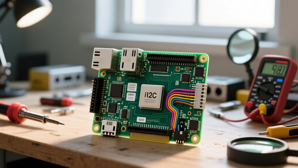
Community member FluxBuilder_88 wanted to integrate 16 legacy 24V AC irrigation solenoid valves into Home Assistant using a Pi 4 Model B. Directly driving 16 optocouplers via GPIO was impossible due to the 50mA bank limit and a lack of available pins. The solution? An MCP23017 I/O expander mapped via I2C.
The I2C Pin Config Strategy
By utilizing the primary I2C bus, the project frees up the remaining GPIO pins for local sensors. The MCP23017 handles the heavy lifting, sinking up to 25mA per pin to drive the optocoupler LEDs.
| Pi 4 Header Pin | BCM GPIO | Function | MCP23017 Connection |
|---|---|---|---|
| Pin 1 | 3.3V Power | VDD | MCP23017 Pin 9 (VDD) |
| Pin 3 | GPIO 2 (SDA1) | I2C Data | MCP23017 Pin 13 (SDA) |
| Pin 5 | GPIO 3 (SCL1) | I2C Clock | MCP23017 Pin 12 (SCL) |
| Pin 6 | Ground | Common GND | MCP23017 Pin 10 (VSS) |
| Pin 11 | GPIO 17 | Interrupt A | MCP23017 Pin 20 (INTA) |
Pro-Tip from the builder: To prevent I2C bus lockups caused by long wire runs to the irrigation control box, a PCA9600 I2C bus extender was used to convert the signal to a differential pair over CAT5e cable.
Showcase 2: Resolving SPI and I2S Audio Collisions
Building a retro-gaming arcade cabinet with high-fidelity audio is a classic SBC project. However, community member ArcadeAudioPhile hit a massive roadblock: both the ILI9341 SPI TFT display and the HiFiBerry DAC+ (I2S) required overlapping pin configurations on the 40-pin header.
Remapping via Device Tree Overlays
The standard SPI0 bus uses GPIO 10 (MOSI), 9 (MISO), and 11 (SCLK). The I2S interface uses GPIO 18 (PCM_CLK), 19 (PCM_FS), 20 (PCM_DIN), and 21 (PCM_DOUT). While they don't directly collide, the SPI0 Chip Select (CE0 on GPIO 8, CE1 on GPIO 7) often conflicts with custom arcade button mappings and the DAC's initialization sequences.
The fix involved enabling the secondary SPI bus (SPI1) and routing the display there, freeing up SPI0 for other peripherals. This requires editing the /boot/firmware/config.txt file (or /boot/config.txt on older OS versions) with specific device tree overlays documented in the Raspberry Pi configuration guide.
# Enable I2S Audio DAC
dtoverlay=hifiberry-dac
# Enable SPI1 with 3 Chip Selects for the TFT Display
dtoverlay=spi1-3cs
# Map SPI1 to the TFT Display pins
dtoverlay=tft9341,spi1,cs=1,dc=24,backlight=25
This pin config hack ensures the audio DMA controller never misses a clock cycle due to SPI display refresh interrupts.
Showcase 3: Swapping UARTs for Industrial RS485 Sensors
Environmental monitoring in greenhouses requires long-distance wired communication. RS485 is the industry standard, but it requires a stable hardware UART. The Raspberry Pi's primary UART (PL011) is often mapped to the Bluetooth module on Pi 3 and Pi 4 boards, leaving the GPIO header with the 'mini-UART', which lacks a stable baud rate clock and drops packets at 115200 baud.
The UART Swap Configuration
Community engineer AgriTechNode solved this by forcing the PL011 hardware UART onto the GPIO header (GPIO 14 TXD, GPIO 15 RXD) and disabling Bluetooth. This is critical for Modbus RTU communication with soil moisture sensors.
'If you don't swap the UARTs, the mini-UART's baud rate drift will cause CRC errors on the Modbus bus every time the CPU load spikes. The PL011 swap is non-negotiable for industrial RS485.' - AgriTechNode
To achieve this, add enable_uart=1 and dtoverlay=disable-bt to your configuration file. This routes the stable PL011 UART to pins 8 and 10, allowing the MAX485 transceiver to communicate flawlessly over 500 meters of twisted pair cabling.
Community Disaster Report: Fried Pins and Ground Loops
For every successful showcase, our forums see a dozen fried boards. The most common failure mode in Raspberry Pi pin config is the 5V Tolerance Myth. Unlike the Arduino Uno (ATmega328P), which tolerates 5V logic inputs, the Pi's BCM2711 and RP1 silicon will suffer immediate gate oxide breakdown if a 5V signal is fed into a 3.3V GPIO input.
Real-World Fix: When interfacing with 5V sensors like the HC-SR04 ultrasonic module, always use a voltage divider. A 3.3kΩ resistor to ground and a 2.2kΩ resistor in series with the Echo pin safely drops the 5V signal to ~2.0V, well within the Pi's 3.3V logic high threshold (which triggers at anything above 1.8V).
Another frequent disaster is backpowering. Connecting a powered USB hub that lacks a back-power blocking diode can feed 5V into the Pi's USB port, bypassing the board's polyfuse and voltage regulation, leading to catastrophic SoC failure.
The Pi 5 Paradigm Shift: RP1 and the Death of raspi-gpio
If you are configuring pins on the newer Raspberry Pi 5, you must update your software toolkit. The Pi 5 offloads GPIO control to the RP1 southbridge chip. Consequently, the legacy raspi-gpio command-line tool is deprecated and will not function correctly.
For debugging your pin config on a Pi 5, the community has standardized around the new pinctrl utility. Running pinctrl get will reveal the exact multiplexing state, drive strength, and pull-up/pull-down status of the RP1 pins. Understanding this shift is vital for makers migrating their hardware stacks to the latest generation of SBCs.
Final Thoughts and Resources
Mastering the Raspberry Pi pin config is about respecting the silicon limits while leveraging the flexibility of Linux device tree overlays. Whether you are expanding I2C for home automation, remapping SPI for retro-gaming, or stabilizing UARTs for industrial sensors, the community's collective trial and error paves the way for robust deployments.
For visual mapping of the 40-pin header across all Pi models, we highly recommend bookmarking Pinout.xyz, an indispensable interactive resource maintained by the community. Have a unique pin configuration hack or a custom HAT design? Share your schematics and code snippets in the ElectricalFlux forums to be featured in our next showcase.