
Why Alternating Current Units Differ from DC Measurements
When transitioning from direct current (DC) breadboard projects to mains electricity, motor controls, or complex AC electronics, DIYers and junior electricians often hit a wall of confusing terminology. You might ask, "What is the standard alternating current unit?" The truth is, there isn't just one. Because AC voltage and current constantly change direction and magnitude in a continuous sinusoidal wave, quantifying it requires a specialized set of units and mathematical conventions that simply do not apply to the flat, steady lines of DC power.
In a DC circuit, a multimeter reading of 12 Volts means the electrical pressure is exactly 12 Volts at every given millisecond. In an AC circuit, the voltage is constantly swinging from zero to a positive peak, back through zero, down to a negative peak, and back again. Therefore, the alternating current unit of measurement must account for time, frequency, and the mathematical averaging of a wave. Misunderstanding these units is a primary cause of undersized wire, tripped breakers, and catastrophic component failure in DIY electrical projects.
The Core Alternating Current Unit Breakdown
To properly size wires, select breakers, and troubleshoot circuits, you must understand the foundational units used to describe AC power. Below is the definitive reference chart for AC measurements.
| Measurement | Unit Name | Symbol | AC-Specific Context & Application |
|---|---|---|---|
| Electromotive Force | Volts | V | Measured in RMS (Root Mean Square) for standard mains. Dictates insulation requirements and dielectric breakdown thresholds. |
| Current Flow | Amperes | A | Measured in RMS. Determines wire gauge (AWG/mm²) and thermal limits of conductors to prevent insulation melting. |
| Frequency | Hertz | Hz | Cycles per second (60Hz in North America, 50Hz in Europe). Affects inductive reactance and motor speeds. |
| Real Power | Watts | W | The actual work performed or heat generated. Used for calculating energy consumption and thermal dissipation. |
| Apparent Power | Volt-Amperes | VA | The geometric sum of real and reactive power. Critical for sizing transformers, UPS systems, and generator alternators. |
The RMS Concept: The Most Misunderstood AC Metric
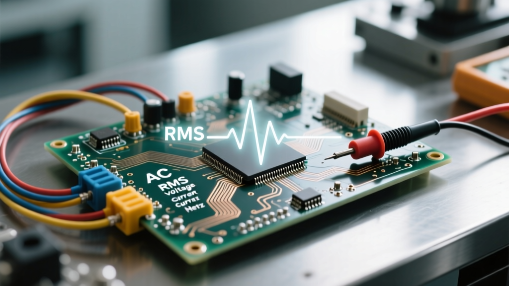
If you take a standard digital multimeter and measure a North American wall outlet, it will display roughly 120V. However, if you connect an oscilloscope to that same outlet, you will see the voltage peak at roughly 169.7V. Why the discrepancy? The answer lies in the most critical alternating current unit concept: Root Mean Square (RMS).
RMS is not a physical unit like Volts or Amps; rather, it is a statistical method of quantifying the effective value of a varying waveform. According to the Electronics Tutorials AC Formulas guide, the RMS value of an AC sine wave is calculated by squaring the instantaneous values, finding their mean (average), and then taking the square root of that mean.
The Golden Rule of RMS: An AC voltage of 120V RMS will produce the exact same amount of heat in a resistive load (like a toaster or incandescent bulb) as 120V of steady DC. It is the "DC equivalent" heating value.
For a pure sine wave, the relationship between peak voltage and RMS voltage is defined by the formula: V_RMS = V_Peak / √2 (or roughly V_Peak × 0.707). When you are sizing capacitors for an AC rectifier circuit, you must use the peak voltage to ensure the capacitor's dielectric isn't breached. When you are sizing wire for the AC supply, you use the RMS current to calculate thermal heating.
Frequency and Time: Hertz as the Defining AC Unit
Unlike DC, which has a frequency of zero, AC is defined by its oscillation rate. The Hertz (Hz) is the SI unit of frequency, representing one complete cycle per second. In North America, the grid operates at 60 Hz, meaning the current changes direction 120 times per second (two zero-crossings per cycle). In much of the rest of the world, the standard is 50 Hz.
Why does Hertz matter for DIY wiring and component selection? It fundamentally alters how components oppose current flow, known as reactance.
- Inductive Reactance (X_L): Coils and motors oppose AC current based on frequency. The formula is
X_L = 2πfL. If you take a motor designed for 60Hz and run it on a 50Hz supply, its inductive reactance drops, causing it to draw significantly higher RMS amperage, overheat, and potentially burn out the windings. - Skin Effect: At 60Hz, the skin effect (where AC current prefers to travel on the outer edge of a conductor) is negligible for standard residential wire gauges. However, as frequency increases into the kilohertz (kHz) or megahertz (MHz) range—such as in high-frequency switching power supplies or radio transmitters—current is forced to the surface of the wire. This effectively reduces the cross-sectional area of the conductor, requiring specialized stranded or Litz wire to maintain ampacity.
Real vs. Apparent Power: Watts versus Volt-Amperes
One of the most dangerous mistakes in electrical sizing is confusing Watts (W) with Volt-Amperes (VA). In a purely resistive DC circuit, Power = Voltage × Current. In AC circuits, this is only true if the voltage and current waveforms are perfectly in phase.
When you introduce inductive loads (motors, transformers) or capacitive loads (power factor correction banks, long underground cables), the current wave shifts out of alignment with the voltage wave. This creates Reactive Power (VAR).
- Watts (W): Real power. The actual energy consumed and converted into work or heat.
- Volt-Amperes (VA): Apparent power. The total power the source must supply, including the energy that sloshes back and forth between the source and the reactive load without doing any real work.
If you are sizing a backup generator or a UPS system for a workshop, you must size it based on Volt-Amperes (VA), not Watts. A 1,500W AC motor with a poor Power Factor (PF) of 0.6 will actually draw 2,500 VA from the grid. If you buy a 1,500W generator, it will stall and trip the breaker immediately upon motor startup, despite the "Watt" ratings matching. Always check the NIST SI Units guidelines to ensure you are respecting the strict definitions of real versus apparent power in your calculations.
Practical Troubleshooting: Reading AC Units on a Multimeter
Understanding the alternating current unit of RMS is useless if your testing equipment cannot measure it accurately. This brings us to the vital distinction between True-RMS and Average-Responding multimeters.
Cheaper, average-responding multimeters do not actually calculate the Root Mean Square. Instead, they measure the average value of the rectified AC wave and multiply it by a fixed constant (1.1107 for a perfect sine wave) to guess the RMS value. This works perfectly for clean, linear loads like incandescent lights and space heaters.
However, modern electronics are non-linear. LED drivers, variable frequency drives (VFDs), and computer power supplies draw current in harsh, spiky pulses rather than smooth sine waves. If you use an average-responding meter on a circuit with heavy harmonic distortion, your RMS current reading can be off by 30% to 50%. You might think a wire is safely carrying 12 Amps, when it is actually carrying 18 Amps of True-RMS current, leading to melted insulation and fire hazards.
As noted by testing equipment manufacturer Fluke in their True-RMS technical guide, True-RMS meters sample the waveform thousands of times per second, square the values, average them, and take the square root in real-time, providing an accurate heating-value measurement regardless of waveform distortion.
Summary Checklist for AC Circuit Design
- Insulation Rating: Always verify the peak voltage (RMS × 1.414), not just the RMS voltage, when selecting dielectric materials or capacitors.
- Wire Sizing: Use True-RMS Amperes to calculate conductor heating and select AWG sizes according to NEC Table 310.16.
- Source Sizing: Size transformers, inverters, and generators using Volt-Amperes (VA) to account for reactive power and poor power factors.
- Tooling: Never trust an average-responding multimeter when troubleshooting circuits containing solid-state switches, dimmers, or VFDs.
Mastering the alternating current unit is not just about memorizing definitions; it is about understanding the physical reality of how oscillating electrons interact with resistance, inductance, and capacitance. By respecting the nuances of RMS, Hertz, and Power Factor, you ensure your DIY electrical projects are not only functional but fundamentally safe and efficient.