
Beyond the Textbook: Troubleshooting the AC Sine Wave
When junior technicians and DIYers ask, "how does the alternating current work?" the standard textbook answer is that electrons periodically reverse direction, creating a sine wave. While theoretically correct, this definition is practically useless when you are standing in front of a buzzing 3-phase motor, a melted neutral busbar, or a breaker that trips for no apparent reason. To truly master AC troubleshooting, you must stop viewing electricity as invisible water flowing through a pipe and start analyzing it as a dynamic, time-varying waveform. According to the U.S. Energy Information Administration, alternating current is the backbone of modern power grids because it allows for efficient voltage transformation, but its oscillating nature introduces complex fault modes that direct current (DC) simply does not exhibit.
In this guide, we will deconstruct the mechanics of alternating current through the lens of a diagnostician. We will explore how deviations in peak voltage, frequency, phase angle, and waveform symmetry manifest as physical failures in real-world electrical systems.
Deconstructing the Sine Wave: Why RMS Measurements Can Mislead You
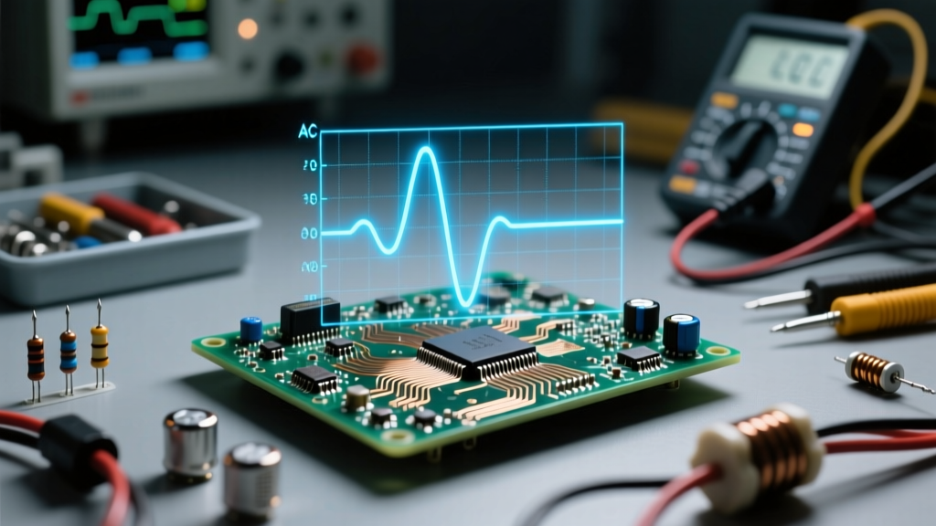
To understand how AC works under stress, you must first understand the relationship between Root Mean Square (RMS) voltage and Peak voltage. A standard North American residential outlet is rated for 120V AC. However, this is the RMS value—the equivalent DC voltage that would produce the same heating effect in a resistive load. The actual sine wave peaks much higher.
The mathematical relationship is defined as: V_peak = V_rms × √2. Therefore, a 120V RMS circuit actually peaks at roughly 169.7V (often rounded to 170V) during every single cycle. This distinction is a massive source of troubleshooting errors, particularly when dealing with capacitors and solid-state electronics.
The Capacitor Explosion Failure Mode
Consider a scenario where a DIYer replaces a failed motor run capacitor. If they mistakenly install a capacitor rated for 150V DC on a 120V AC line, the capacitor will violently fail. Why? Because the AC waveform pushes the dielectric material to 169.7V peak, exceeding the capacitor's 150V DC insulation limit. When diagnosing blown capacitors or varistors (MOVs) on control boards, always verify that the component's DC voltage rating exceeds the AC line's peak voltage, not just its RMS rating. Always use a True-RMS multimeter, like the Fluke 87V, to get accurate readings on non-linear loads, as explained in Fluke's guide on True-RMS measurements.
The 60Hz Heartbeat: Diagnosing Frequency and Motor Faults
Alternating current in North America completes 60 full cycles per second (60Hz). This frequency is not just a number; it is the mechanical heartbeat of every AC induction motor and transformer on the grid. The synchronous speed of an AC motor is directly dictated by the formula: Speed = (120 × Frequency) / Number of Poles.
Generator Governor Failures and Motor Overheating
When troubleshooting a facility powered by a backup diesel generator, you might notice that AC motors are running hot and tripping their thermal overloads, even though your multimeter reads a perfect 120V or 480V. The culprit is often frequency droop. If the generator's mechanical governor fails to maintain exactly 60Hz under load, and the frequency drops to 57Hz, the motor's synchronous speed drops. To maintain its mechanical output torque, the motor draws significantly higher amperage, leading to rapid insulation breakdown. When diagnosing unexplained thermal trips on generator-backed circuits, always measure frequency (Hz) alongside voltage.
Troubleshooting Matrix: AC Waveform Anomalies
Use the following diagnostic matrix to correlate physical symptoms with underlying AC waveform failures.
| Waveform Anomaly | Root Cause | Physical Symptom | Diagnostic Tool |
|---|---|---|---|
| Voltage Sag (Brownout) | Undersized utility transformer or heavy inrush current from neighboring loads. | Lights dim periodically; contactors chatter and drop out. | Power Quality Logger (e.g., Fluke 1730) |
| Phase Shift (Low Power Factor) | Highly inductive loads (large motors) causing current to lag behind voltage. | Utility penalty fees; excessive I²R heating in supply conductors. | Power Analyzer measuring Phase Angle (θ) |
| Flat-Top Clipping | Switch-mode power supplies drawing current only at the peak of the sine wave. | Overheating neutral conductors; premature transformer failure. | Oscilloscope or Power Quality Analyzer |
| High-Frequency Ringing | VFDs (Variable Frequency Drives) switching rapidly, causing parasitic inductance. | Motor bearing fluting; nuisance tripping of GFCI/AFCI breakers. | High-Bandwidth Oscilloscope (e.g., Rigol DS1054Z) |
Harmonic Distortion: When the AC Waveform Loses Its Shape
In a pristine electrical system, alternating current forms a perfect, smooth sine wave. However, modern facilities are flooded with non-linear loads—LED drivers, computer servers, and Variable Frequency Drives (VFDs). These devices do not draw current continuously throughout the sine wave; instead, they gulp current in short, aggressive pulses at the very peak of the voltage waveform. This distorts the AC wave, creating harmonic frequencies (multiples of the fundamental 60Hz).
The Triplen Harmonic Neutral Fire Hazard
According to Fluke's power quality documentation, the most dangerous byproducts of non-linear loads are "triplen" harmonics (the 3rd, 9th, 15th, etc.). In a standard 3-phase, 4-wire wye system, the fundamental 60Hz currents cancel each other out in the neutral conductor. However, triplen harmonics are "zero-sequence"—meaning they are perfectly in phase with one another. Instead of canceling out, they add arithmetically in the neutral.
Troubleshooting Rule of Thumb: If you are investigating a commercial building where the neutral conductor is overheating or the neutral busbar shows signs of thermal discoloration despite balanced phase loading, you are likely dealing with severe 3rd harmonic distortion. The neutral current can theoretically reach 1.73 times the phase current.
To fix this, electricians must install K-rated transformers designed to handle harmonic heating, or oversize the neutral conductor to 200% of the phase conductor capacity.
Ghost Voltages and Capacitive Coupling in AC Systems
One of the most confusing phenomena for those learning how alternating current works is the "ghost voltage." Imagine you are troubleshooting a dead circuit. You disconnect the hot wire from the breaker, turn the breaker back on, and probe the disconnected wire with your digital multimeter (DMM). The meter reads 45V AC. Is the wire energized? No.
This happens because of capacitive coupling. Alternating current creates an expanding and collapsing electromagnetic field around the conductor. If a de-energized wire runs parallel to an energized wire inside the same conduit, the alternating electric field induces a phantom voltage on the dead wire. Because a modern DMM has an extremely high input impedance (typically 10 Megohms), it draws almost zero current, allowing this phantom voltage to register on the screen.
The Solenoid Tester Solution
To troubleshoot this and prove the circuit is truly dead, use a low-impedance solenoid voltage tester (often called a Wiggy). The solenoid tester draws enough physical current to instantly collapse the capacitively coupled phantom field, dropping the reading to 0V. Understanding the difference between high-impedance and low-impedance testing is a hallmark of an expert AC troubleshooter.
Conclusion: Seeing the Unseen
Answering the question of how alternating current works requires looking past the basic definition of reversing electron flow. True mastery lies in understanding the sine wave's peak amplitudes, its strict adherence to frequency, and its vulnerability to harmonic distortion. By upgrading your diagnostic toolkit to include True-RMS meters, power quality analyzers, and low-impedance testers, you can translate the invisible physics of AC waveforms into actionable, real-world repairs.