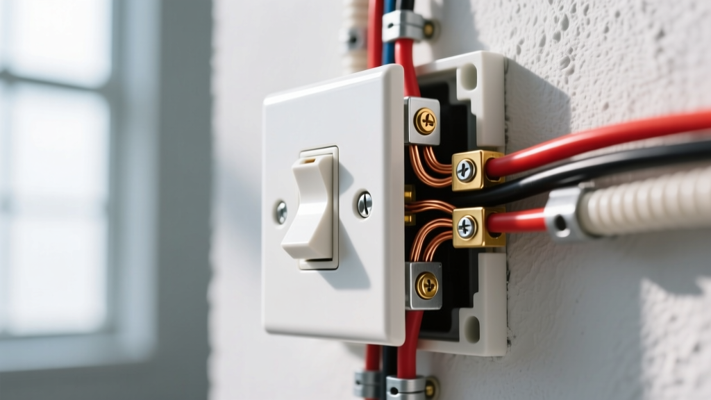
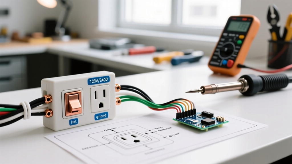
Wiring a GFCI plug (Ground Fault Circuit Interrupter) requires connecting the incoming hot (black) and neutral (white) wires to the LINE terminals, routing any downstream protected wires to the LOAD terminals, and securing the bare or green equipment grounding conductor to the green grounding screw. You must never swap the line and load connections, and you must never create a "bootleg ground" by jumpering the neutral to the ground screw. A miswired GFCI will either fail to protect downstream devices while appearing to do so, or it will energize appliance chassis during normal operation, creating a severe shock hazard.
The Lethal Physics: Why Grounding and Terminal Precision Matter
Before stripping a single wire, you must understand the specific hazards a GFCI is designed to prevent and what happens when the installation is compromised. A GFCI monitors the current balance between the hot and neutral conductors. If it detects a leakage of 4 to 6 milliamps (mA)—meaning current is escaping the intended path, potentially through a human body to the earth—it trips the internal solenoid in under 25 milliseconds. This rapid interruption prevents the ventricular fibrillation threshold (typically around 30-50 mA) from being reached.
In older homes with ungrounded 2-prong outlets, some DIYers attempt to "create" a ground by installing a jumper wire between the silver neutral terminal and the green ground screw on a GFCI. This is incredibly dangerous. If the upstream neutral wire ever breaks or develops high resistance, the full 120V return current will seek an alternate path. Because of the jumper, the equipment grounding conductor (and any metal appliance chassis plugged into it) will become energized at line voltage. Always leave the ground screw empty if no equipment grounding conductor exists in the box; the GFCI will still provide shock protection via its internal sensing coil, though it must be labeled "No Equipment Ground."
Ground vs. Neutral vs. Bond: Clearing the Confusion
To wire a GFCI plug correctly, you must treat the neutral and ground as entirely separate conductors downstream of the main service panel.
- Neutral (Grounded Conductor): The white wire. This is a current-carrying conductor that completes the circuit by returning current to the source under normal operation.
- Ground (Equipment Grounding Conductor): The bare or green wire. This is a non-current-carrying conductor. It only carries current during a fault condition (e.g., a hot wire touches a metal toaster casing) to provide a low-impedance path back to the panel, forcing the breaker to trip.
- Bonding: The physical connection between the neutral and ground systems. In a standard US residential system, the neutral and ground are bonded only at the main service disconnect. They must never be bonded at a subpanel or at a receptacle.
GFCI Receptacle Terminal Specifications & Fault Tolerance
The following table outlines the exact terminal assignments for a standard 20A, 125V GFCI receptacle (such as the Leviton 8299-W or Pass & Seymour 2095-W) and the specific hazards introduced by miswiring.
| Terminal Type | Wire Color (US NEC) | Function | Hazard if Miswired or Swapped |
|---|---|---|---|
| LINE Hot (Brass) | Black | Receives incoming 120V power from the breaker panel. | If swapped with LOAD, the GFCI protects itself but leaves downstream devices completely unprotected while appearing reset. |
| LINE Neutral (Silver) | White | Receives incoming return current from the panel. | If swapped with LOAD neutral, downstream devices lose GFCI protection and the receptacle may fail to reset. |
| LOAD Hot (Brass) | Red or Black | Sends GFCI-protected power to downstream standard receptacles. | If connected to incoming power, the GFCI will not function or reset; downstream devices are unprotected. |
| LOAD Neutral (Silver) | White | Sends GFCI-protected return path to downstream receptacles. | If connected to incoming neutral, internal sensing coil cannot monitor the full circuit; shock hazard persists. |
| Grounding (Green) | Bare or Green | Provides fault-current path to the panel ground bus. | If jumpered to neutral (bootleg ground), metal appliance chassis can become energized at 120V if upstream neutral fails. |
Step-by-Step Procedure for a 20A GFCI Receptacle
This procedure assumes you are replacing a standard receptacle with a 20A Tamper-Resistant (TR) GFCI on a 120V, 20A branch circuit using 12 AWG copper wire (NM-B or THHN). If you are working with 15A circuits and 14 AWG wire, a 15A GFCI is required, but the terminal logic remains identical.
If you are replacing an existing receptacle and there are multiple cables in the box, do not disconnect the wires until you have identified which cable brings power from the panel (Line) and which goes to downstream outlets (Load). Turn off the breaker, disconnect the wires, turn the breaker back on, and carefully use a non-contact voltage (NCV) tester to identify the hot Line wire. Turn the breaker back off before proceeding.
- De-energize and Verify Dead: Turn off the circuit breaker. Apply a lockout/tagout device if you are not the only person in the home. Test the existing receptacle with a plug-in tester or a multimeter (set to AC Volts) measuring between the hot slot and ground slot. The reading must be 0V.
- Prepare the Conductors: Strip exactly 5/8 inch of insulation from the 12 AWG wires. Do not nick the copper. If the wire is stranded, twist it tightly or apply a ferrule. GFCI terminal screws use a pressure plate design; nicked or frayed wires can slip out from under the plate.
- Terminate the LINE Conductors: Connect the incoming black (hot) wire to the brass LINE terminal. Connect the incoming white (neutral) wire to the silver LINE terminal. For a 20A Leviton device, torque these screws to 14 in-lbs using a calibrated torque screwdriver. Loose connections cause arcing and thermal failure.
- Terminate the Ground: Connect the bare or green equipment grounding conductor to the green grounding screw. If there are multiple ground wires (e.g., one incoming, one outgoing), pigtail them together with a wire nut and a short 12 AWG jumper to the GFCI ground screw. Torque to 14 in-lbs.
- Terminate the LOAD Conductors (If applicable): If you are protecting downstream outlets, connect the outgoing black wire to the brass LOAD terminal and the outgoing white wire to the silver LOAD terminal. If you are not protecting downstream outlets, leave the LOAD terminals completely empty and leave the yellow warning tape over them.
- Check for Multi-Wire Branch Circuits (MWBC): If your box contains two hot wires (e.g., black and red) sharing a single white neutral, you have an MWBC. You cannot install a standard single-pole GFCI on an MWBC with a shared neutral. The GFCI will trip immediately because the neutral current will not match the individual hot current. You must use a 2-pole GFCI breaker in the panel or separate the neutrals.
- Secure and Close: Carefully fold the wires into the back of the box. GFCI receptacles are significantly deeper than standard receptacles (often 1.3 to 1.5 inches deep). If the box is shallow, you may need to install a 1-inch box extender to meet NEC 314.20 requirements for flush mounting.
Verification, Testing, and Code Compliance
Once the device is physically installed and the breaker is restored, you must verify the wiring integrity before plugging in any loads. Relying solely on the built-in "TEST" button on the receptacle face is insufficient because the internal test button only checks the internal solenoid and sensing circuit; it does not verify that the equipment grounding conductor is properly connected to the panel.
How to Verify with a Receptacle Tester
Use a dedicated GFCI receptacle tester, such as the Gardner Bender GFI-3501 or Klein Tools RT210.
- Plug the tester into the newly wired GFCI. The lights should indicate "Correct" (typically two yellow/amber lights, depending on the brand).
- Press the black "TEST" button on the tester itself. This button creates a deliberate 6mA leakage fault by routing current from the hot slot to the ground pin.
- The GFCI should trip instantly with an audible click, and the tester lights should go out. If the tester lights go out but the GFCI did not physically click and reset button didn't pop, your ground wire is missing or broken, and the tester is finding a phantom path.
- Press the "RESET" button on the GFCI face to restore power.
Code Guidance and AHJ Authority
According to NEC-style guidance found in Article 210.8, GFCI protection is required for all 125V, 15A and 20A receptacles in kitchens, bathrooms, garages, outdoors, crawl spaces, and unfinished basements. Furthermore, Article 406.4(D)(4) dictates that when replacing a faulty receptacle in any of these locations, the replacement must be a GFCI, even if no equipment ground exists in the box. However, the National Electrical Code is a model standard. Your local Authority Having Jurisdiction (AHJ)—typically the city or county electrical inspector—has the final legal authority on compliance, amendments, and inspection sign-offs.
When to Call a Licensed Electrician
While replacing a receptacle is a common DIY task, you must stop and hire a licensed electrician under the following conditions:
- No Ground Wire in the Box: If you are upgrading a 2-prong ungrounded outlet to a 3-prong GFCI, the NEC allows this only if the GFCI is labeled "No Equipment Ground" and "GFCI Protected." However, if you are installing new circuits or running new wire, a proper ground must be pulled. An electrician can evaluate if a new ground wire can be fished through the walls.
- Aluminum Wiring: If your home was built in the late 1960s or 1970s and uses aluminum branch wiring, standard copper-rated GFCIs can cause galvanic corrosion and high-resistance fires. You need CO/ALR rated devices and specific anti-oxidant paste, which requires professional handling.
- Immediate Breaker Trips: If the breaker trips the moment you turn it on (before even pressing the GFCI test button), you have a hard short circuit, a pinched wire in the box, or a shared neutral MWBC issue. Diagnosing this requires a megohmmeter and circuit tracing tools.
- Panel Upgrades: If you are adding GFCI protection via a GFCI circuit breaker in the main panel rather than at the receptacle, you are working inside the main service enclosure where the main lugs remain lethal even when the main breaker is off. This is strictly the domain of a licensed professional.
Properly wiring a GFCI plug is about respecting the physics of fault currents. By keeping the line and load distinct, maintaining the separation between neutral and ground, and verifying the installation with an external tester, you ensure the device will perform its life-saving function when a fault actually occurs. For more detailed safety data on ground fault protection in residential environments, refer to the Consumer Product Safety Commission (CPSC) guidelines or the Electrical Safety Foundation International (ESFI) resources.