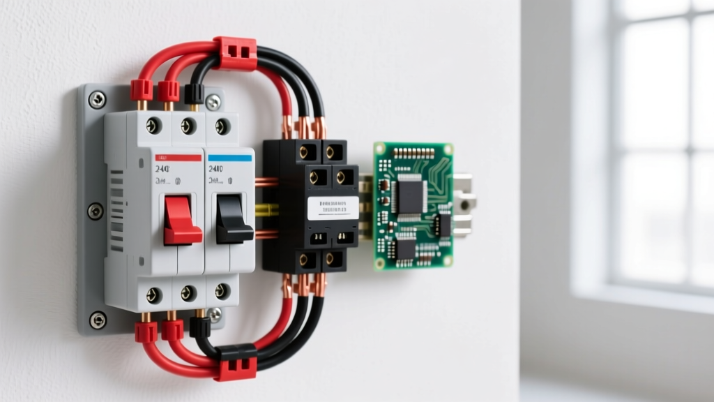

When wiring a double switch for high-amperage 240V circuits—like a well pump, air compressor, or heavy baseboard heater—you are not using a standard residential wall toggle. In the electromechanical and industrial world, a 'double switch' refers to a double-pole contactor or a heavy-duty DPDT (Double-Pole Double-Throw) relay. These devices allow a low-voltage control circuit to safely switch two isolated high-power lines simultaneously.
The direct answer for a standard 30A, 240V resistive or motor load is to use a 40A double-pole contactor with a 24V AC coil, such as the Schneider Electric TeSys D (LC1D40). This guide breaks down the exact rating columns you need to read, how to wire the coil versus the contacts, and the definitive decision path for selecting your component.
Coil vs. Contact Side: Decoding the Electromechanical Double Switch
The most common mistake when wiring a double switch is confusing the control circuit with the load circuit. Electromechanical contactors provide galvanic isolation between the two.
- The Coil Side (A1 and A2): This is the electromagnet. When you apply the rated coil voltage (e.g., 24VAC, 120VAC, or 12VDC), it generates a magnetic field that pulls the contact bridge down. Coil wiring uses small gauge wire (typically 18 AWG to 14 AWG) and is often controlled by a smart relay, thermostat, or Arduino/ESP32 setup via an intermediary pilot relay.
- The Contact Side (L1/L2 to T1/T2): These are the heavy-duty silver-alloy contacts that carry the actual 240V load. L1 and L2 are your line (source) inputs; T1 and T2 are your load (output) terminals. This side requires wire sized to the load's ampacity (e.g., 10 AWG THHN for a 30A circuit) and proper torque on the terminal screws (typically 1.2 to 1.5 N·m for 10 AWG).
Rating Table: Which Column Governs Your Load?
If you look at a contactor datasheet, you will see multiple current ratings. Which rating column governs this load? The governing column is never the raw thermal current (Ith). It is the IEC Utilization Category column that matches your specific load type. A contactor rated for 40A resistive (AC-1) will weld its contacts shut if used to switch a 40A motor (AC-3) due to the inrush current and inductive arcing.
| IEC Category | Load Type | Typical Application | Breaking Capacity | Governing Rule |
|---|---|---|---|---|
| AC-1 | Non-inductive / Resistive | Space heaters, ovens, resistive loads | 1.5x Ie | Use Ith or AC-1 rating. Power factor is near 1.0. |
| AC-3 | Squirrel-cage Motors | Compressors, pumps, conveyors | 8x to 10x Ie | MUST use AC-3 rating. Handles high starting inrush and inductive break. |
| AC-8a | Hermetic Refrigerant Compressors | HVAC units, refrigeration | 6x Ie | Requires specific hermetic ratings and manual reset overload compatibility. |
Source reference: IEC 60947-4-1 defines the utilization categories for low-voltage contactors and motor starters.
Load Type Decision Path: Resistive, Inductive, or Motor?
Follow this decision tree to select the correct double-pole switch architecture. Do not treat fuses and breakers as interchangeable here; a standard C-curve breaker will nuisance-trip on motor inrush. Use a D-curve breaker or a Class RK5 time-delay fuse for inductive/motor loads to accommodate the Locked Rotor Amps (LRA).
| IF your load is... | THEN select this Utilization Category | AND size the contactor to... | Overcurrent Protection Required |
|---|---|---|---|
| Resistive (Heater, Strip) | AC-1 | 125% of continuous load current | Standard C-curve breaker or standard fuse |
| Inductive (Transformer, Solenoid) | AC-3 (Derated) | 200% of continuous load current | D-curve breaker or time-delay fuse |
| Motor (Pump, Compressor) | AC-3 or AC-8a | 125% of Motor FLA (Full Load Amps) | D-curve breaker + dedicated overload relay |
Step-by-Step Wiring and DC Flyback Protection
Before touching any wires, de-energize the panel, lock out the breaker, and verify the circuit is dead with a known-working CAT III multimeter. Local electrical codes (NEC Article 430 for motors) may require a licensed electrician for permanent hardwired installations.
- Mount the Contactor: Snap the contactor onto a 35mm DIN rail inside a NEMA-rated enclosure. Never leave a contactor loose in a panel where vibration can loosen line terminals.
- Wire the Load Side (T1/T2): Strip 1/2 inch of insulation from your load wires. Insert into T1 and T2. Torque to the manufacturer's specification (usually marked on the device or datasheet). A loose 240V terminal will arc, melt the lug, and cause a fire.
- Wire the Line Side (L1/L2): Connect your 240V source from the breaker to L1 and L2. Ensure the breaker is sized correctly (e.g., 40A breaker for 8 AWG wire feeding a 32A continuous load).
- Wire the Coil (A1/A2): Run your control wires (e.g., 18 AWG) from your smart switch, thermostat, or pilot relay to A1 and A2. Polarity does not matter for AC coils.
The Flyback Diode Rule for DC Coils
If you are using a DC coil contactor or relay (e.g., 12VDC or 24VDC coil controlled by an ESP32 or Arduino), you must install a flyback diode across A1 and A2. When the magnetic field collapses, it generates a high-voltage reverse spike that will instantly fry your microcontroller's GPIO pins or driver transistor.
- Component: 1N4007 rectifier diode (pennies at any electronics shop).
- Orientation: The silver stripe (cathode) MUST point toward the positive voltage terminal (A1). Wire it in parallel with the coil.
Testing Dead and Live: When to Repair vs. Replace
Electromechanical double switches are wear items. The contacts pit and arc over time. Here is how to test them and the definitive rule on maintenance.
Testing Dead (Power OFF)
- Set your multimeter to Continuity or Resistance (Ohms).
- Place probes on L1 and T1. Push the contact bridge down manually with a flathead screwdriver.
- Pass: Reading drops to < 0.5 ohms.
- Fail: Reading is infinite (open) or fluctuates wildly (pitted/carbonized contacts).
Testing Live (Power ON - Extreme Caution)
- Set your multimeter to AC Voltage.
- Energize the coil so the contactor pulls in.
- Measure the voltage drop across the closed contacts (probe L1 and T1 simultaneously).
- Pass: Voltage drop is < 0.2V. This indicates a clean, low-resistance connection.
- Fail: Voltage drop is > 1.0V. The contacts are burning power as heat and are nearing thermal failure.
When to Repair vs. Replace
Always replace. In the sub-100A category, contactors and heavy-duty relays are sealed or riveted units. You cannot sand down pitted silver-alloy contacts, and you cannot rewind a burnt coil. If your live voltage drop test exceeds 1.0V, or if the contactor emits a loud, persistent 60Hz buzz (indicating a dirty pole face or failing shading coil), swap the entire unit immediately. Attempting to repair a 240V double-pole switch is a false economy that ends in melted enclosures or electrical fires.
For further reading on proper motor circuit protection and overcurrent device sizing, refer to the NFPA 70 (National Electrical Code) Article 430, which dictates the exact multipliers required for motor branch circuits.