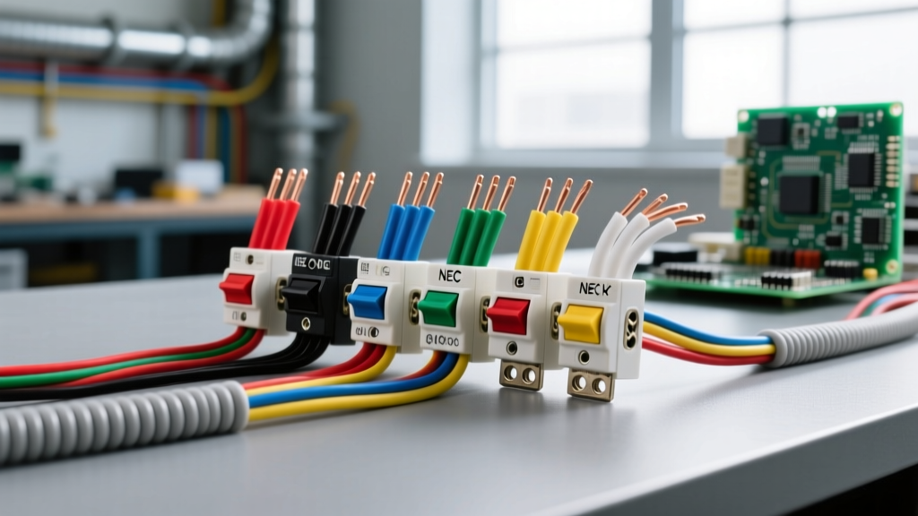
When international DIYers and sparkies search for how to wire up a two way light switch, they are usually referring to what North American electricians call a 3-way switch. In the UK and Australia, a "two-way" setup allows you to control a single light from two locations using L1, L2, and Common terminals. In the US and Canada, we achieve the exact same functionality using 3-way switches with one Common and two Traveler terminals.
The Direct Answer: To wire a two-way (3-way) switch setup on a standard 15A residential lighting circuit, use 14/3 NM-B cable between the two switches and 14/2 NM-B for the power and light drops. Land the black (hot) wire on the dark-colored Common screw, the red and white (traveler) wires on the brass Traveler screws, and the bare copper on the green Ground screw. Use a 15A rated switch like the Leviton 5603-2W.
Tools, Materials, and Device Ratings
Before you pull any wire, verify your circuit ampacity. Most modern lighting circuits are 15A (14 AWG), but older homes or kitchens may have 20A lighting circuits (12 AWG). Never put 14 AWG wire on a 20A breaker.
Required Materials
- Switches: Two 15A 3-way toggle switches (e.g., Leviton 5603-2W) or a smart/dimmer 3-way kit (e.g., Lutron Claro MACL-153M with companion). Ensure they are rated for the load (standard LED loads are well under 1A).
- Wire: Southwire 14/2 NM-B (power and light drops) and 14/3 NM-B (traveler run between switches). If on a 20A circuit, step up to 12/2 and 12/3.
- Connectors: Ideal Industries In-Sure Push-in connectors (3-port and 4-port) or wire nuts rated for the specific AWG combination.
- Wallplates: 1-gang and 2-gang toggle plates (nylon or polycarbonate, not brittle standard plastic).
Mains Safety and De-Energization Protocol
Decision Path: Choosing Your Wiring Method
The physical layout of your walls dictates where power enters the system. There are two primary topologies for a 3-way circuit. Review the table below to determine your scenario, but note that Scenario A is the industry default for simplicity and code compliance regarding neutral routing.
| Scenario | Power Source Location | Cable Needed Between Switches | Verdict / Action |
|---|---|---|---|
| A: Power-to-Switch | Line voltage enters at Switch 1 box. | 14/3 NM-B (Black, Red, White, Bare) | DEFAULT PICK. Use this method. It is the most straightforward, requires no white-wire re-identification, and keeps the neutral at the first box. |
| B: Power-to-Light | Line voltage enters at the ceiling fixture first. | 14/3 NM-B (White must be re-identified as hot with black tape) | Avoid if possible. Requires re-identifying the white wire as a hot conductor per NEC 200.7, which confuses future DIYers and is a common code violation if forgotten. |
Concrete Pick: For the step-by-step instructions below, we are executing Scenario A (Power-to-First-Switch). If your existing rough-in matches Scenario B, you must re-identify the white traveler wire with black electrical tape at both ends to signal that it is a hot conductor, not a neutral.
Step-by-Step Wiring: Power-to-First-Switch Method
With the breaker OFF and the circuit verified dead, follow these exact termination steps. Strip all wire insulation back exactly 3/4 inch using your wire strippers. Do not nick the copper.
- Prepare Switch 1 (Power In Box): You will have a 14/2 power feed (Black, White, Bare) and a 14/3 traveler cable (Black, Red, White, Bare) entering this box.
- Connect the Black wire from the 14/2 power feed directly to the Dark-colored Common screw on Switch 1.
- Connect the Red and Black wires from the 14/3 traveler cable to the two Brass-colored Traveler screws on Switch 1. (Order does not matter between the two brass screws).
- Connect the White wire from the 14/2 power feed to the White wire of the 14/3 traveler cable using a wire nut. This passes the neutral through to the light. Do not attach any white wires to the switch.
- Prepare Switch 2 (Light Drop Box): You will have the 14/3 traveler cable arriving from Switch 1, and a 14/2 drop cable (Black, White, Bare) heading up to the light fixture.
- Connect the Black wire from the 14/2 light drop directly to the Dark-colored Common screw on Switch 2.
- Connect the Red and Black wires from the 14/3 traveler cable to the two Brass-colored Traveler screws on Switch 2.
- Connect the White wire from the 14/3 traveler cable to the White wire of the 14/2 light drop using a wire nut. This completes the neutral path to the fixture.
- Terminate Grounds (Both Boxes): In both switch boxes, twist all Bare copper wires together with a 6-inch Bare copper pigtail. Secure the pigtail to the Green Ground screw on the switch. If you are using a metal junction box, you must also bond the box to the ground pigtail using a green grounding clip or a 10-32 grounding screw. NEC 404.9 requires the switch yoke to be grounded.
- Final Tightening: Torque all terminal screws firmly. A loose connection on a 15A circuit can cause arcing and heat buildup. Give each wire a firm tug to ensure it is seated under the screw head, not just resting under the insulation.
Verify and Test: Meter Readings and Function Check
Do not just throw the breaker and hope for the best. Use your multimeter to verify the circuit logic before applying full power.
- Continuity Check (Power OFF): Set your Fluke 117 (or equivalent) to the Ohms/Continuity setting. Place one probe on a brass traveler screw at Switch 1 and the corresponding traveler at Switch 2. You should read < 1 ohm (a solid beep). Repeat for the second traveler pair. Place a probe on the Common screw of Switch 1 and the Common of Switch 2; it should read OL (Open Line / Infinite) because the path goes through the light bulb's impedance, not a direct wire.
- Voltage Check (Power ON): Turn the breaker ON. Set your meter to V AC. Place one probe on the Common screw of Switch 1 and the other on the bare ground. You must read 114V to 126V (nominal 120V). If you read 0V, your breaker is off or the feed is dead. If you read 240V, you have a severe miswiring issue—kill the breaker immediately.
- Functional Test: Operate Switch 1. The light should toggle. Operate Switch 2. The light should toggle regardless of Switch 1's position.
The Most Common Botch (And How to Fix It)
If you finish the job and the light behaves erratically, you have almost certainly fallen victim to the most common 3-way wiring error: swapping the Common and Traveler wires on one of the switches.
Symptom: The "One-Position" Failure
The light turns on and off perfectly when you use Switch 1. However, when you flip Switch 2, the light either stays dead, stays on, or simply does nothing. The circuit only works if Switch 1 is left in a specific "UP" or "DOWN" position.
The Diagnosis and Fix
This happens because the installer put the hot feed (or the light drop) on a brass Traveler screw, and put a traveler wire on the dark Common screw. * The Fix: Turn off the breaker. Identify the wire that comes from the power source (at Switch 1) or the wire that goes to the light fixture (at Switch 2). That specific wire must be on the dark-colored (usually black or oxidized copper) Common screw. The two wires that travel between the two switch boxes must be on the brass screws. * Pro-Tip: Before disconnecting an old 3-way switch to replace it, always use a piece of blue painter's tape to flag the wire attached to the dark Common screw. Never assume the wire color matches the terminal; previous DIYers may have used whatever scrap wire was in their truck.